Introduction
You walk onto the plant floor and hear that distinct, grinding noise coming from the conveyor drive. The gearbox casing is hot enough to cook an egg, and production is now at a standstill because a critical worm gear seized up. This scenario is not just an inconvenience; it represents a direct hit to your operational efficiency and a significant drain on your maintenance budget.
But here is the harsh reality.
Replacing the failed part without diagnosing the root cause guarantees it will fail again, likely sooner than the last time. Worm gear sets are unique in the power transmission world because they rely heavily on sliding action rather than rolling contact. This makes them exceptionally sensitive to thermal limits, lubrication quality, and installation precision. By understanding specific failure modes—from lubrication breakdown to metallurgical mismatches—you can implement a prevention strategy that extends equipment lifecycle. We apply decades of manufacturing data and failure analysis to guide you toward permanent reliability.

Why Does Lubrication Breakdown Cause Thermal Failure?
Worm gears operate under high sliding friction, which generates significantly more heat than rolling element gears like spur or helical sets. The sliding action creates a wiping motion that tries to scrape the oil film off the tooth surface. When the lubricant film ruptures, metal-to-metal contact occurs instantly. This leads to rapid temperature spikes, scoring, and irreversible damage to the softer bronze wheel.
Here is the kicker.
Heat is the enemy. If you cannot keep the gearbox hand-touchable (roughly 60°C or 140°F), your lubrication regime is failing. The viscosity of the oil drops as temperature rises. If the viscosity drops below the minimum film thickness requirement for that specific load and speed, the gear set will destroy itself regardless of how robust the metal is.
Identifying Common Lubrication Issues
Many failures that look like “wear” are actually chemistry problems.
- Wrong Oil Type: Using mineral oil instead of Polyalkylene Glycol (PAG) for high-duty cycles. PAG oils have a lower coefficient of friction and better thermal stability.
- Low Oil Levels: Prevents the “splash” required to reach the mesh point, especially in worm-over-wheel configurations.
- Contamination: Bronze particles from break-in wear act as an abrasive paste if not filtered out.
- Viscosity Breakdown: Operating temperatures exceeding 90°C (194°F) permanently degrade the oil’s additive package.
Lubrication Failure Diagnostics
Use this data to correlate physical symptoms with oil condition.
| Failure Sign | Likely Lubrication Cause | Corrective Action |
|---|---|---|
| Discolored/Burnt Oil | Thermal degradation | Switch to synthetic PAG; install external cooler |
| Scuffing on Teeth | Film rupture (low viscosity) | Increase ISO viscosity grade (e.g., from 320 to 460) |
| Foaming | Overfilling or contamination | Drain to correct level; check seals for air leaks |
| Sludge Buildup | Oxidation from overheating | Shorten change interval; flush gearbox |
| Bronze Flakes in Oil | Abrasive wear | Filter oil; check for misalignment |
Key Takeaway: Managing the thermal environment is the first line of defense against premature seizing. Verify your oil type matches the sliding velocity of the gear set.
How Do Surface Fatigue and Pitting Destabilize Operations?
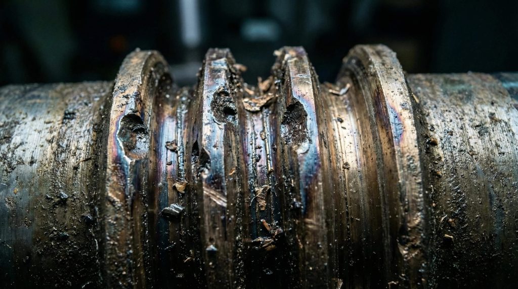
Pitting isn’t a sudden event; it is a progressive disease of the gear tooth surface caused by repeated contact stress (Hertzian stress). Unlike abrasive wear, which removes material layers evenly, pitting begins below the surface. Small cracks form at the point of maximum shear stress within the bronze material. Eventually, these cracks propagate to the surface, causing shards of bronze to flake off and destroy the mesh geometry.
But what triggers this?
It usually signifies that the gearbox is being asked to do more than it was designed for. If the localized pressure exceeds the fatigue limit of the bronze, the material structure collapses. This often happens even if the average load is within limits, but peak loads or vibration cause stress concentrations.
Primary Fatigue Drivers
- Service Factor Violations: Running the gearbox above its rated service factor (e.g., using a 1.0 S.F. gearbox on a rock crusher requiring 2.0).
- Stop-Start Cycling: Frequent starting prevents a fluid film from forming, forcing the gears to operate in boundary lubrication mode repeatedly.
- Material Impurities: Poor casting quality in the bronze rim leads to voids or inclusions that act as stress risers.
- Inadequate Break-in: applying full load immediately without allowing the worm and wheel to “bed in” and polish each other.
Distinguishing Corrective vs. Destructive Pitting
Not all pitting requires immediate panic. “Corrective pitting” appears as tiny pinpricks during the initial run-in period as high spots are knocked down. This typically stops once the load is distributed. “Destructive pitting” involves large craters with jagged edges that grow rapidly.
Yantong Tech Engineering Insight:
Early pitting is often visible only under magnification. We recommend conducting a visual inspection of the contact pattern after the first 500 hours of operation. If you see “destructive pitting” (large craters covering >25% of the tooth) rather than “corrective pitting” (polishing of high spots), the load is too high for the material specification. Immediate load reduction or a gearbox upgrade is required.
Key Takeaway: Pitting is a clear signal that the localized contact pressure exceeds the material’s fatigue limit. Catching it early allows for load adjustments before tooth fracture.
Is Misalignment the Silent Killer of Worm Shafts?
Even the highest quality gear set, manufactured to ISO Grade 6 precision, will fail if the worm shaft and worm wheel are not perfectly orthogonal (at 90 degrees). Misalignment concentrates the load onto a fraction of the tooth face—perhaps only 20% or 30% of the available area. This effectively doubles or triples the stress in that localized area, causing rapid overheating and wear.
Check this first.
Alignment issues often manifest immediately after installation or maintenance. If a gearbox is noisy right from the start, do not run it hoping it will “break in.” It won’t. It will break down.
Alignment Red Flags
- Shifted Contact Pattern: The wear mark is crowded to the “entry” (toe) or “exit” (heel) side of the tooth rather than centered.
- Excessive Noise: A loud hum or whine usually indicates incorrect center distance or shaft offset.
- Uneven Thread Wear: The worm shaft shows heavy scoring on one side of the thread flank but not the other.
- Bearing Play: Loose bearings allow the worm shaft to deflect under load, altering the mesh geometry dynamically.
Interpreting Contact Patterns
Use a blueing agent (Prussian blue) to check the mesh during assembly.
| Contact Pattern Location | Diagnosis | Probable Assembly Error |
|---|---|---|
| Center of Tooth | Ideal Condition | Correct assembly |
| Toe Contact (Entry) | Load Concentration | Center distance too tight or shaft offset |
| Heel Contact (Exit) | Insufficient Bearing Support | Worn bearings or center distance too loose |
| Top Land Contact | Pitch Diameter Mismatch | Wrong gear set installed or severe housing distortion |
| Root Contact | Bottoming Out | Center distance significantly too tight |
Key Takeaway: A centered contact pattern is non-negotiable for achieving the rated life of the gear set. Use shims precisely to center the worm wheel relative to the worm shaft.
Can Shock Loading Lead to Catastrophic Tooth Fracture?
Worm gears are often favored for their self-locking capabilities and high ratios, making them popular in heavy lifting, mining, and crushing applications. However, these environments are prone to shock loads—sudden, massive torque spikes caused by jams or emergency stops. Since the bronze wheel is significantly softer than the hardened steel worm, a shock load acts like a guillotine.
Don’t ignore the signs.
Unlike wear, which takes months, shock loading can destroy a gearbox in milliseconds. It typically results in the shearing of multiple teeth from the worm wheel or plastic deformation where the tooth bends permanently out of shape.
Sources of Shock Loads
- Emergency Stops (E-Stops): Braking systems that clamp down instantly without a soft-start/stop ramp create infinite inertia against the gears.
- Material Jams: Rocks in a crusher or pallets jamming a conveyor stop the output shaft while the motor keeps driving.
- Direct Online Starting: Starting high-inertia loads without a Variable Frequency Drive (VFD) sends a torque hammer through the system.
- Back-driving Forces: External forces trying to drive the output shaft faster than the input, causing chatter and impact.
Engineering Protections
If shock loading is unavoidable in your process, standard DIN/ISO gear ratings do not apply. You must design for the peak, not the average.
Yantong Tech Engineering Insight:
If your application involves frequent shock loads, rely on mechanical fuses. Consider using a “shear pin” mechanism or a torque-limiting coupling on the input shaft. Alternatively, ask us about modifying the tooth profile to increase the root strength of the bronze wheel. We can thicken the tooth root or adjust the pressure angle to favor strength over efficiency for high-impact applications.
Key Takeaway: Mechanical overload fails parts faster than any wear mechanism; protection requires external limiting devices like fluid couplings or torque limiters.
Why is Material Metallurgy Critical for Gear Survival?
The friction inherent in a worm drive necessitates a dissimilar metal pair to prevent galling (cold welding). This is typically a hardened steel shaft (worm) and a bronze wheel. Failure often stems from procurement decisions that prioritize price over metallurgy. Using generic, low-grade bronze that lacks centrifugal casting density or proper alloy composition ensures the gear will fail under load.
The secret lies in metallurgy.
The manufacturing method of the bronze ring is just as important as the chemical composition. Sand-cast bronze is cheaper but porous; it contains tiny air pockets that weaken the tooth structure. Centrifugally cast bronze is denser, harder, and has a finer grain structure, offering superior wear resistance.
Common Material Deficiencies
- Sand Casting: Results in lower tensile strength and porosity, leading to early fatigue.
- Insufficient Case Depth: The steel worm shaft must be case-hardened. If the hardened layer is too thin, the high contact pressure will crack the “case” like an eggshell, exposing the soft core.
- Hardness Mismatch: If the steel shaft is not polished to a mirror finish, it acts like a file against the bronze.
- Missing Alloys: Heavy-duty applications require Nickel or Phosphorus bronze (e.g., CuSn12Ni2) for added toughness.
Material Specifications for Reliability
Verify these standards with your supplier.
| Component | Recommended Material (Yantong Std) | Processing Standard |
|---|---|---|
| Worm Shaft | 20CrMnTi / 18CrNiMo7-6 | Carburized, Hardened & Ground (HRC 58-62) |
| Worm Wheel (Rim) | CuSn12Ni2 (Nickel Bronze) | Centrifugal Casting (Mandatory for high load) |
| Worm Wheel (Hub) | Cast Iron / 45# Steel | Normalized or Quenched & Tempered |
| Precision Class | ISO Grade 6-7 | Ground profiles for optimized contact |
Key Takeaway: You cannot machine performance into a gear if the raw material integrity is missing. Always demand material certificates that prove centrifugal casting methods were used.
How Do You Implement a Zero-Failure Maintenance Strategy?
Waiting for a failure is the most expensive maintenance strategy you can employ. It results in expedited shipping costs, overtime labor, and lost production revenue. Shifting to condition-based monitoring involves tracking temperature, vibration, and oil condition to predict end-of-life long before the machine actually stops.
Money is saved here.
A worm gear set will usually tell you it is dying weeks before it actually fails. The temperature will creep up. The vibration signature will change. The oil will start to glitter with bronze particles.
The Proactive Maintenance Checklist
- Quarterly Oil Analysis: Send samples to a lab. High copper ppm indicates wear on the wheel; high iron ppm indicates wear on the worm or bearings.
- Backlash Measurement: Measure the free play at the output shaft annually. An increase in backlash indicates tooth thinning.
- Bearing Pre-load Audit: Check input and output shaft end-play during scheduled shutdowns to ensure bearings haven’t loosened.
- Thermal Management: Regularly clean cooling fins and fans. A layer of dust acts as an insulator, trapping heat inside the gearbox.
- Visual Inspection: Open the inspection hatch to check for pitting or poor contact patterns.
Solving the Legacy Part Problem
One of the biggest challenges in maintenance is dealing with obsolete equipment where drawings no longer exist.
Yantong Tech Engineering Insight:
For legacy machines where drawings are lost, do not guess on replacements. We offer Reverse Engineering services to map worn parts. We identify the original material composition, measure the worn geometry, calculate the original theoretical profile, and manufacture dimensionally correct replacements that restore (or improve) factory performance.
Key Takeaway: Consistent monitoring converts unplanned downtime into scheduled, manageable maintenance. Use data, not guesswork, to decide when to replace a gear set.
Conclusion
Worm gear failures—whether driven by thermal breakdown, misalignment, shock loading, or metallurgical flaws—are almost always preventable with the right technical approach. Ignoring the root cause of a seized gearbox ensures history will repeat itself, continually draining your maintenance budget and stressing your production targets. Reliability is not an accident; it is the result of correct design, precise assembly, and disciplined maintenance.
You do not have to navigate these engineering challenges alone. Contact Yantong Tech today to review your application. Whether you need high-precision custom manufacturing to solve a noise issue or reverse engineering for worn components on legacy machinery, we provide the “peace of mind” that comes from authenticated quality and expert engineering support.
FAQ
Q1: Is it safe to use Extreme Pressure (EP) additives in worm gearboxes?
It depends on the chemistry. Some sulfur-phosphorus EP additives are active and can chemically attack yellow metals like bronze at high temperatures, causing corrosion. Always verify the oil is certified “yellow metal safe” or stick to compounded oils designed specifically for worm gears.
Q2: What is the maximum safe operating temperature for a worm gear?
Generally, 90°C (194°F) is the upper limit for standard mineral oils and lip seals. Above this temperature, oxidation accelerates rapidly, cutting oil life in half for every 10°C rise. Synthetic PAG oils can handle higher temperatures (up to 110°C), but seal materials (like Viton) must be upgraded to match.
Q3: Can I reverse the worm wheel to use the unworn side of the teeth?
No. Worm gears “bed in” to a specific rotation and contact pattern during their initial life. Reversing them usually leads to poor contact, excessive noise, and rapid failure because the “coast” side of the tooth often has a different profile or has not been lapped for load-bearing.
Q4: Why does my new worm gear set hum loudly?
This typically indicates poor contact patterns. It is often caused by the center distance being set slightly wrong, the worm shaft being offset axially, or the bearings being too tight/loose. It can also be a sign that the lead angle of the worm does not perfectly match the wheel, often a result of mixing parts from different manufacturers.
Q5: Is a harder bronze always better for wear resistance?
No. The bronze must be significantly softer than the steel shaft to prevent scoring the worm. It needs the right balance of toughness and lubricity. If the bronze is too hard, it won’t conform to the steel worm, leading to high stress concentrations. If it is too soft, it yields under load. The alloy must be matched to the application duty cycle.
