Inaccurate gear dimensions often lead to catastrophic mechanical failures within your industrial drivetrains. You likely struggle with vibration or premature wear because your initial dimensioning lacks the necessary precision required for high-speed operation. Calculating your spur gear tooth thickness correctly provides a definitive pathway toward operational stability and silent power transmission. We provide this expert guide to transform your noisy assemblies into high-performance systems through absolute geometric accuracy.
What defines standard spur gear tooth thickness?
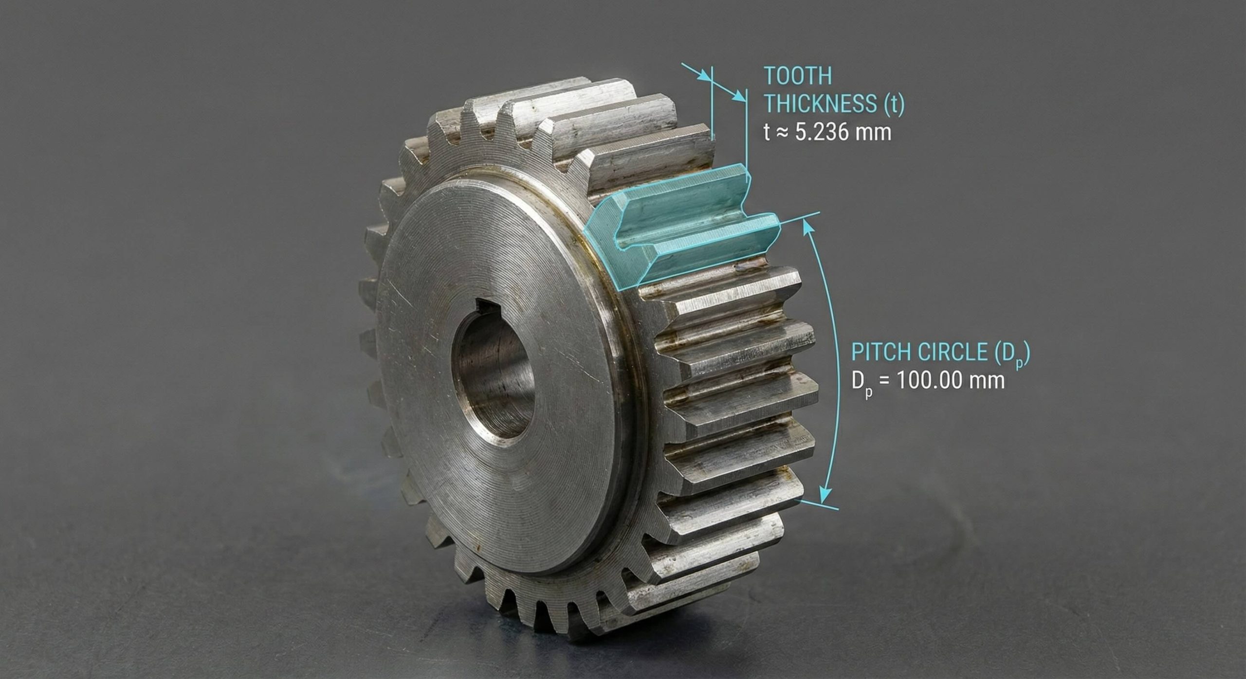
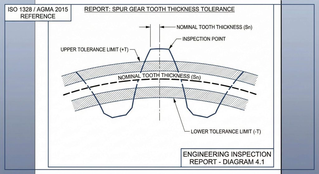
Standard spur gear tooth thickness is the theoretical arc length measured along the reference circle between the two opposing flanks of one tooth. You must distinguish this from chordal measurements which follow a straight line across that same arc during physical inspections. Designers usually specify these dimensions at the pitch diameter where the majority of contact occurs between mating gears. Think about this. If your measurement ignores the natural curvature of the pitch circle, your resulting assembly might fail inspection.
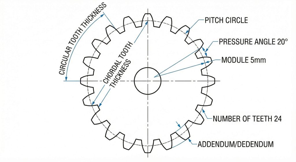
- Circular Thickness: Measured as an arc along the pitch diameter.
- Chordal Thickness: Measured as a straight line between tooth faces.
- Pitch Circle: The primary reference datum for all thickness data.
Theoretical Arc Relationships
Every module increment shifts the geometry slightly, requiring you to prioritize the reference circle as your primary anchor. Most B2B manufacturers utilize standard pressure angles like twenty degrees to simplify these geometric relations during production. Virtual tooth counts often dictate how these arcs appear on smaller pinions versus larger gears. Understanding this relationship ensures your spur gear tooth thickness remains consistent across different gear sizes.
| Parameter | Definition | Application |
|---|---|---|
| Circular Thickness | Arc length along pitch circle | Theoretical design |
| Chordal Thickness | Straight line between tooth flanks | Physical measurement |
| Pitch Diameter | Reference circle for meshing | Layout planning |
Key Takeaway: Standard thickness calculations always anchor to the pitch circle to maintain consistency across different gear sizes and modules.
How to measure spur gear tooth thickness accurately?
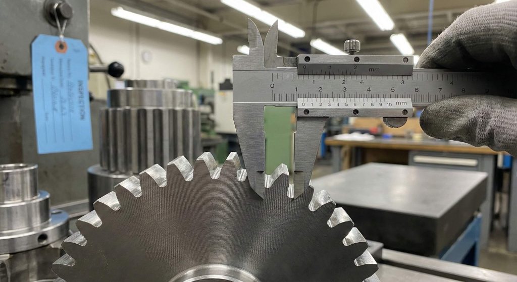
Measuring spur gear tooth thickness accurately requires selecting the right inspection tool based on the required precision grade and gear accessibility. You have multiple options for verifying these dimensions on the factory floor, ranging from direct caliper methods to indirect over-pin measurements. High-speed applications demand indirect methods because they significantly reduce human error during the tactile sensing process. But here’s the kicker. Consistency remains the most important factor when documenting these measurements across multiple production batches to ensure reliability.
- Direct Methods: Handheld tools for immediate workshop feedback.
- Indirect Methods: Laboratory equipment for high-precision validation.
- Tactile Consistency: Uniform pressure application during the measurement phase.
Tool Selection Criteria
Your choice of tool depends entirely on the gear’s accessibility and its required precision grade within your specific application. Vernier calipers work well for rough shop checks but often lack the resolution required for aerospace-grade components. You need to select a method that aligns perfectly with your specific manufacturing tolerances and production volume. Selecting the right tool ensures your data reflects the actual performance of the component under load.
| Method | Tool Used | Best For |
|---|---|---|
| Chordal | Gear Tooth Caliper | General workshop use |
| Span | Micrometer | External gears with many teeth |
| Over-Pin | High-Precision Pins | High-accuracy validation |
Key Takeaway: Selecting the right measurement tool depends on the gear’s final application and the required precision level for smooth operation.
Can chordal methods verify spur gear tooth thickness?
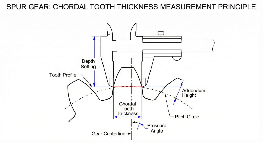
Chordal methods verify spur gear tooth thickness by using a specialized caliper that references the tooth tip to reach the pitch circle depth. You must calculate the exact height from the tip to the pitch circle before setting your caliper depth for a reading. If your addendum height is off by just microns, your thickness reading becomes useless for high-precision drivetrain applications. What’s the real story? This method remains popular because it allows for quick spot checks without removing the gear from the machine.
- Tip Reference: The outside diameter serves as the measurement datum.
- Addendum Height: The vertical distance from the tip to the pitch line.
- Jaw Alignment: Ensuring parallel contact with the involute tooth profile.
Systematic Error Management
You should ensure that your gear blanks meet their outside diameter specifications before performing spur gear tooth thickness chordal checks. Failure to do so introduces a systematic error that propagates through your entire quality control process and affects meshing. Tip diameter variations directly impact the accuracy of the reading, making blank preparation a critical prerequisite. Maintaining a perfectly machined outside diameter is the only way to ensure your chordal measurements remain consistent.
| Step | Action | Metric Goal |
|---|---|---|
| 1 | Measure Tip Diameter | +/- 0.01 mm |
| 2 | Set Caliper Depth | Match Addendum |
| 3 | Record Thickness | Compare to Specs |
Key Takeaway: Chordal verification requires a perfectly machined outside diameter since the tool depth relies on the gear tip as a reference point.
Why does backlash affect spur gear tooth thickness?
Backlash affects spur gear tooth thickness by requiring an intentional reduction in width to create a necessary gap that prevents mechanical jamming. This clearance between mating teeth allows for lubricant flow and accommodates thermal expansion during continuous industrial operation. You must reduce the theoretical tooth thickness to create this necessary gap, ensuring the system does not seize under load. Here’s the deal. Zero backlash sounds ideal but usually results in overheating and rapid destruction of the tooth flanks.
- Thermal Allowance: Space for the material to swell during operation.
- Lubricant Film: Room for the protective oil layer between teeth.
- Jamming Prevention: Avoiding interference during high-speed rotation cycles.
Designing for Clearance
Industrial standards provide specific tables for recommended backlash based on the center distance and the module of the gears. You should account for lubricant film thickness when deciding on your final dimensions to prevent metal-on-metal contact. Most heavy-duty applications require a slightly thinner tooth to allow for heat-induced swelling during long duty cycles in harsh environments. Without this calculated allowance, your drivetrain will eventually seize because there is no space for heat dissipation.
| Application | Required Backlash | Reason |
|---|---|---|
| Precision Robotics | Very Low | Accuracy |
| Heavy Machinery | Moderate | Heat dissipation |
| High Speed | Controlled | Vibration reduction |
Key Takeaway: Intentionally reducing tooth thickness creates necessary backlash which protects the gear system from thermal expansion and lubricant starvation.
What’s the best span for spur gear tooth thickness?
The best span for spur gear tooth thickness involves measuring across a specific tooth count using a specialized micrometer that contacts the base circle. This technique measures the distance across the involute profile rather than the pitch circle, making it more reliable than chordal calipers. You must determine the correct number of teeth to span to ensure the micrometer faces contact the functional profile accurately. Ready for the good part? This method eliminates the need to reference the gear tip, making it ideal for inconsistent blanks.
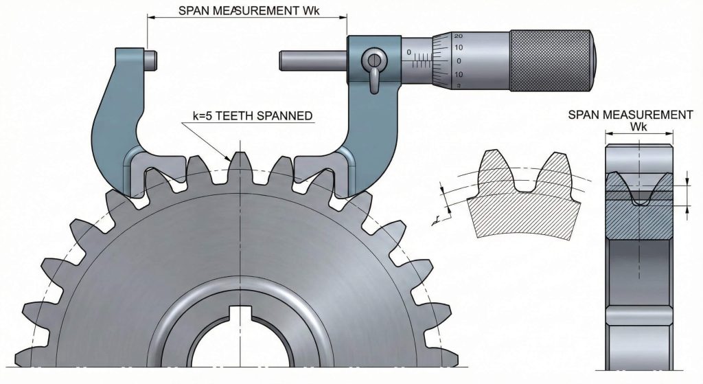
- Base Circle Contact: Measurement occurs on the fundamental involute curve.
- Span Number (k): The integer count of teeth included in the measurement.
- Involute Zone: Ensuring the tool touches the valid part of the tooth.
Span Micrometer Techniques
Calculating the “k” value involves specific formulas based on the pressure angle and the total tooth count of the gear. If you span too few or too many teeth, your reading will fall outside the valid profile zone and yield errors. This method works exceptionally well for high-volume production where the outside diameter might fluctuate between different batches or machines. You should consult our spur gear blog for detailed span formulas tailored to your specific gear geometry.
| Factor | Influence | Requirement |
|---|---|---|
| Pressure Angle | Contact point position | Consistent 20° |
| Tooth Count | k-value determination | Exact integer |
| Base Circle | Measurement plane | Parallel faces |
Key Takeaway: Span measurement offers higher reliability than chordal methods because it remains independent of the gear’s outside diameter variations.
How do pins validate spur gear tooth thickness?
Pins validate spur gear tooth thickness through the over-pin method which uses precision rollers to measure the effective pitch diameter of the gear. This method provides the most accurate way to verify the profile shift and thickness simultaneously in a specialized laboratory setting. You must choose pin diameters that contact the teeth near the pitch circle for the most reliable and representative results. This is where it gets interesting. For gears with an odd number of teeth, the measurement calculation changes significantly to account for asymmetry.
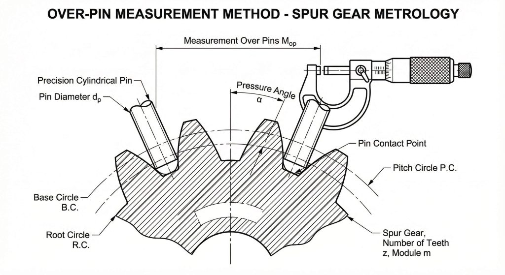
- Precision Rollers: Calibrated pins placed in opposing tooth spaces.
- Over-Pin Dimension: The total distance measured across the outer pin surfaces.
- Pitch Line Contact: The ideal point where the pin should touch the tooth.
Pin Selection for Accuracy
This technique is often considered the gold standard in specialized gear labs due to its repeatable nature across different operators. You should always keep your pins clean and calibrated to maintain the integrity of your high-precision measurement data. For internal gears, the process involves measuring between the pins rather than over them to find the true tooth width. This validation method ensures that your components will mesh perfectly even under the most demanding load conditions.
| Gear Type | Measurement Mode | Pin Contact |
|---|---|---|
| Even Teeth | Diametrically opposite | Near pitch line |
| Odd Teeth | Asymmetric calculation | Profile center |
| Internal Gear | Between pins | Concave flank |
Key Takeaway: The over-pin method serves as the most precise validation technique for tooth thickness and is essential for high-tolerance gear manufacturing.
Can wear reduce the spur gear tooth thickness?
Mechanical wear can reduce the spur gear tooth thickness over long periods of service, leading to increased backlash and audible drivetrain noise. Friction inevitably thins the gear teeth as the surface material is removed by mating components under continuous operational pressure. You will notice increased vibration as the profile degrades, indicating that the gear is reaching its functional end of life. Believe it or not. Excessive wear often points toward lubrication failure or abrasive contamination within the housing that accelerates thinning.
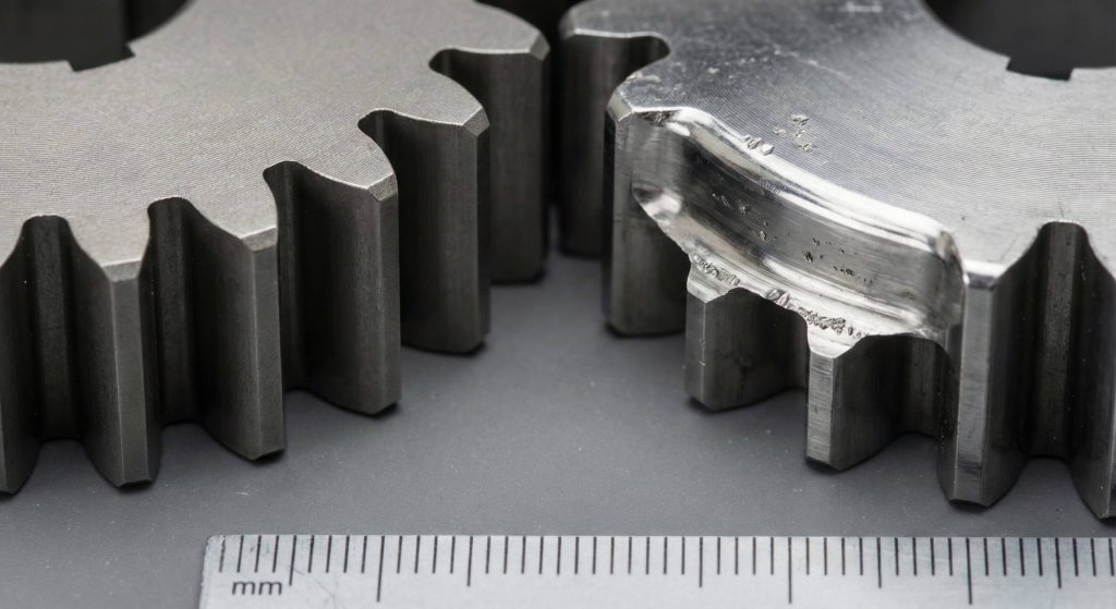
- Surface Fatigue: Pitting and scoring that reduces the effective tooth width.
- Backlash Increase: Growing clearance as the teeth become physically thinner.
- Noise Profiles: Audible indicators of geometric degradation during rotation.
Managing Maintenance Cycles
Monitoring the thickness during scheduled maintenance helps you predict when a gear reaches its end of life before a failure occurs. You should implement regular inspections using span or chordal measurements to track this degradation across your critical drivetrain components. If the thickness drops below a critical threshold, the risk of tooth breakage increases dramatically during high-torque events. For expert support, you can contact us today to evaluate your worn components and plan for replacements.
| Wear Level | Observed Effect | Recommended Action |
|---|---|---|
| Minimal | Normal operation | Regular lube check |
| Moderate | Increased noise | Increase inspection |
| Critical | Vibration/Risk | Immediate replacement |
Key Takeaway: Tracking tooth thickness reduction over time allows maintenance teams to replace gears before catastrophic failure occurs due to structural thinning.
Does module size change spur gear tooth thickness?
Module size will change spur gear tooth thickness because it defines the fundamental geometric scale and physical size of the gear tooth. You will find that larger modules naturally result in thicker, stronger teeth that are capable of handling much higher torque loads. This relationship is linear, meaning doubling the module essentially doubles the tooth thickness while maintaining the same involute geometry. Think about this. Scaling the module allows engineers to balance the gear’s physical weight against the torque requirements of the drivetrain.
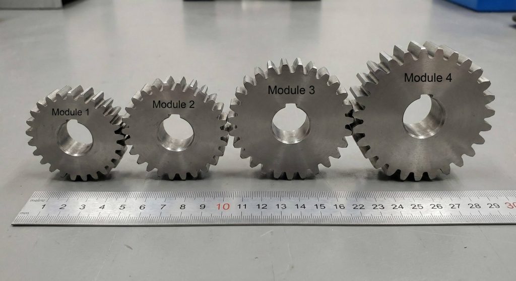
- Linear Scaling: Thickness increases proportionally with the module value.
- Torque Capacity: Larger modules provide greater resistance to tooth shear.
- Meshing Compatibility: Mating gears must share the exact same module.
Scaling the Tooth Profile
Small errors in module selection lead to interference or improper contact patterns that destroy the gear set during initial testing. You must ensure that both mating gears share the exact same module to achieve proper meshing and efficient power transmission. Selecting a larger module increases the load-carrying capacity but also significantly increases the overall weight and inertia of the assembly. This parameter serves as the primary building block for creating a reliable and robust industrial gear system.
| Module | Typical Thickness | Application |
|---|---|---|
| 1.0 | 1.57 mm | Small electronics |
| 5.0 | 7.85 mm | Industrial pumps |
| 10.0 | 15.70 mm | Mining equipment |
Key Takeaway: Module size serves as the primary determinant for the physical thickness and strength of a spur gear tooth profile.
How do tolerances impact spur gear tooth thickness?
Manufacturing tolerances impact spur gear tooth thickness by setting the allowable deviations that ensure consistent meshing across different production batches. You must adhere to specific AGMA or ISO grades depending on your industry requirements to ensure optimal load distribution. A high-precision gear with tight tolerances costs more to produce but operates much quieter than a standard commercial component. What’s the real story? If your thickness varies significantly between teeth, the gear will experience uneven loading and destructive vibration.
- ISO Grades: International standards for defining gear manufacturing quality.
- Load Distribution: Ensuring every tooth carries its fair share of the torque.
- Cost vs Performance: Balancing precision requirements with production expenses.
Verification and Compliance
You should specify tolerances that match the operational speed and torque of your specific application to avoid over-engineering costs. Over-specifying tolerances adds unnecessary expense without providing functional benefits in low-speed machinery like simple conveyor systems. Quality control teams use specialized software to verify these tolerances against the original CAD design to ensure total compliance. Tight control over these deviations ensures that your drivetrain remains silent and reliable for years of continuous operation.
| Tolerance Grade | Accuracy | Usage |
|---|---|---|
| ISO 4 | Extremely High | Aerospace |
| ISO 7 | Moderate | Automotive |
| ISO 10 | Commercial | Conveyors |
Key Takeaway: Matching tooth thickness tolerances to the gear’s operational speed ensures an optimal balance between manufacturing costs and mechanical performance.
What role does heat play in spur gear tooth thickness?
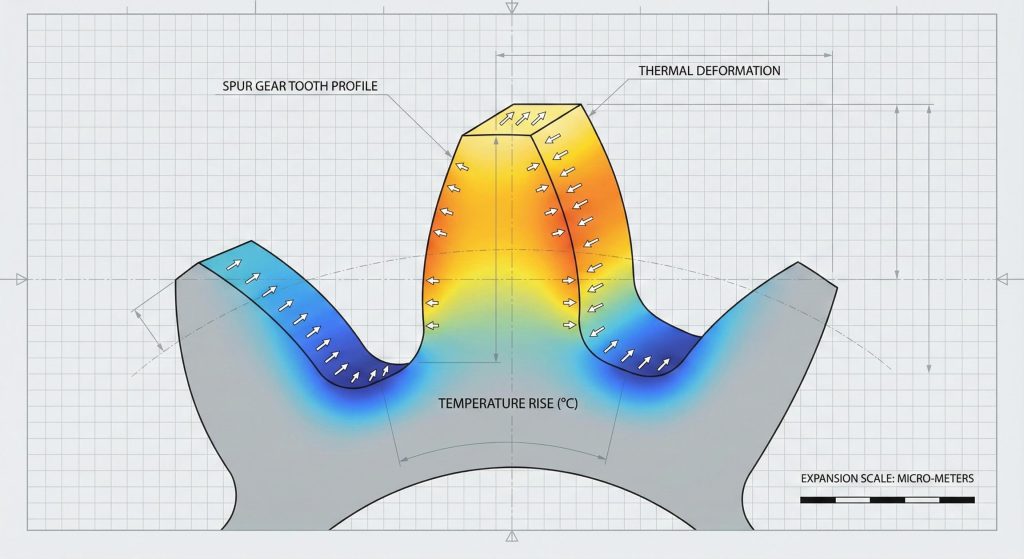
Heat expansion will play a role in spur gear tooth thickness by causing the material to swell and reducing the available backlash. You must account for the coefficient of thermal expansion for your chosen material to prevent the gears from locking up completely. Steel gears expand differently than plastic or bronze alternatives, requiring unique thickness adjustments for each material type during production. Ready for the good part? Understanding this allows you to design gears that mesh perfectly only at their peak operating temperature.
- Thermal Expansion: The physical growth of the gear tooth as it gets hot.
- Initial Thinning: Producing a thinner tooth to allow for expansion.
- Material Sensitivity: How different metals react to operational heat cycles.
Initial Thickness Compensation
If you ignore thermal effects, the gears may tighten during use until they seize, leading to catastrophic failure of the drivetrain. You should calculate the expected expansion and subtract that value from the room-temperature thickness during the production phase. This foresight prevents mechanical seizures in high-temperature environments like engine compartments or industrial furnaces where heat is constant. Proper lubrication and cooling systems help manage these thermal shifts by keeping the gear temperature within a stable range.
| Material | Expansion Rate | Thermal Sensitivity |
|---|---|---|
| Carbon Steel | Moderate | Predictable |
| Nylon/Plastic | High | Critical |
| Stainless Steel | Low | Stable |
Key Takeaway: Predicting thermal expansion allows engineers to adjust the initial tooth thickness so the gear reaches its ideal dimensions at operating temperature.
Frequently Asked Questions
Q1: Can I use a standard micrometer for spur gear tooth thickness?
You can use a standard micrometer only for the over-pin method. For direct tooth measurements, you need a specialized gear tooth caliper or a span micrometer to clear the surrounding teeth without interference.
Q2: What’s the best way to handle tooth thinning in plastic gears?
You should account for much larger backlash allowances in plastic gears because their thermal expansion rates are significantly higher than metals. Use the span measurement method to avoid crushing the soft material during inspection.
Q3: Can I measure internal gears with a chordal caliper?
Measuring internal gears with a standard caliper is extremely difficult due to the concave shape. You should use the between-pins method for the highest accuracy on internal tooth thickness to ensure meshing stability.
Q4: How does profile shift change the spur gear tooth thickness?
Positive profile shift increases the tooth thickness at the pitch circle and strengthens the tooth root against shear stress. You must adjust your measurement calculations to include the shift coefficient “x” when verifying these gears.
Q5: What’s the best way to detect wear without stopping the machine?
You can monitor vibration levels or acoustic signatures to detect thinning teeth while the system is running. However, a physical measurement during scheduled downtime remains the only definitive way to confirm actual thickness loss.
Final Summary for Gear Precision
Summarizing our findings, your success in drivetrain design hinges on the absolute precision of spur gear tooth thickness. We have explored how chordal, span, and over-pin methods provide the data needed for quality control while balancing backlash and thermal expansion. You must integrate these calculations into your standard engineering workflow to prevent costly errors and ensure mechanical longevity. Please contact us today if you require custom gear solutions or more technical guidance for your next project. Our vision is to empower global industries through unmatched transmission reliability and precision manufacturing excellence that stands the test of time.