
To measure the angle of a gear, you calculate the arc tangent of the axial lead relative to the pitch circumference or use precision tools like a bevel protractor. Identifying the exact specifications of a worn gear is a significant challenge when original documentation is missing. Using the wrong angle during a repair can lead to excessive noise, vibrations, and immediate mechanical failure. Fortunately, learning how to measure helix angle of helical gear allows you to reverse-engineer parts with professional accuracy.
How to measure helix angle of helical gear via trigonometry?
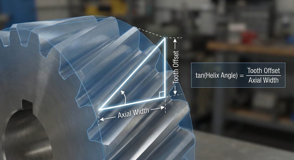
You use basic trigonometry by measuring the axial width and the tooth’s horizontal offset across the face. Finding how to measure helix angle of helical gear starts with defining a right triangle on the tooth flank. You then apply the arctangent formula to the ratio of the offset over the axial thickness to find the degrees.
Which dimensions must you record first?
You need the axial thickness of the gear face and the distance the tooth travels horizontally across that face.
Look at it this way:
- Measure the gear face width with precision.
- Track one tooth’s start and end points.
- Calculate the ratio for the tangent.
Key Takeaway: Trigonometric calculations provide a mathematical foundation that eliminates guesswork during the reverse engineering process.
| Metric | Tool | Purpose |
|---|---|---|
| Axial Width | Calipers | Establishing the triangle base |
| Tooth Offset | Depth Gauge | Calculating the opposite side |
| Helix Angle | Calculator | Resulting angular geometry |
You should double-check your measurements at multiple points around the circumference to ensure consistency.
How to measure helix angle of helical gear with a protractor?
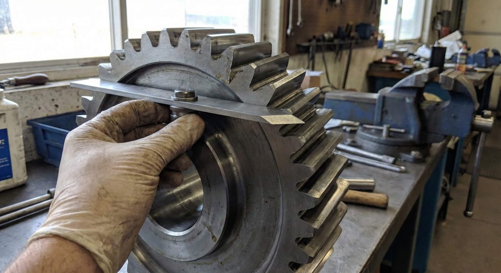
You apply a bevel protractor directly against the tooth flank and the gear’s flat side face. This manual approach for how to measure helix angle of helical gear provides a physical reading of the angle relative to the gear axis. It is a preferred method for machinists working with large industrial components in a shop environment.
How do you align the tool?
You must ensure the base of the protractor is perfectly flush with the gear’s flat side to avoid errors.
The best part?
- Zero the tool on a flat surface first.
- Align the blade with the tooth slope carefully.
- Read the degrees on the precision scale.
Key Takeaway: Using a bevel protractor allows for immediate physical verification without the need for complex software or digital files.
| Alignment | Requirement | Impact |
|---|---|---|
| Base Plate | Flush to side | Prevents tilt error |
| Blade Edge | Parallel to tooth | Accurate angle capture |
| Scale Lock | Secure before reading | Maintains measurement integrity |
You must verify that the gear is cleaned of all debris before setting the protractor blade against the teeth.
How to measure helix angle of helical gear using 3D printing?
You create iterative test segments to physically check the mesh against the original part. When researching how to measure helix angle of helical gear, many makers print small variations like 15 and 20 degrees. You then slide these segments into the mating gear to see which one rotates with the least resistance.
Why is the physical mesh test effective?
You can feel the backlash and friction that digital measurements might miss during a quick assessment.
Check this out:
- Print multiple segments with 1-degree differences.
- Test the roll with the mating gear.
- Select the smoothest operating angle.
Key Takeaway: Additive manufacturing provides a low-cost way to validate theoretical angles through real-world physical interaction.
| Advantage | Benefit | Value |
|---|---|---|
| Tangible Fit | Hands-on testing | Reduces error risk |
| Low Cost | Uses standard filament | Saves metal machining costs |
| Fast Speed | Rapid prototyping | Quick design iteration |
You should account for material shrinkage in your printer settings to maintain accurate tooth profiles.
How to measure helix angle of helical gear via mobile apps?
You use smartphone inclinometers to get a rapid digital reading of the tooth slope. This modern method for how to measure helix angle of helical gear utilizes the phone’s internal gyro sensors. You simply align the edge of your device with the tooth flank while the gear is secured on a flat surface.
Is a smartphone app accurate enough?
You should use apps for initial field estimates rather than final precision manufacturing blueprints.
Here is the deal:
- Calibrate the app on a level surface.
- Rest the phone against the tooth edge.
- Record the digital angle output.
Key Takeaway: Digital sensors in mobile devices offer a convenient way to get an “in-the-ballpark” measurement when you are away from the shop.
| Tool | Reliability | Best For |
|---|---|---|
| Inclinometer App | Low-Medium | Field inspections |
| Gyroscope | High Response | Quick estimates |
| Digital Level | Medium | Large gear faces |
You should combine this digital data with a manual rubbing to confirm the results before placing any orders.
How to measure helix angle of helical gear using paper traces?
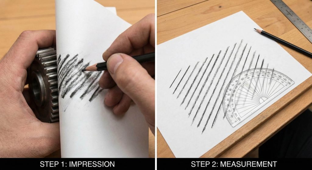
You wrap a piece of paper around the gear and rub a pencil over the teeth to create a trace. This manual technique for how to measure helix angle of helical gear translates a 3D surface into a 2D geometric map. Once the paper is flat, you use a standard protractor to measure the angle of the resulting parallel lines.
How do you ensure the trace is clear?
You must keep the paper tight against the gear surface to prevent the tooth pattern from shifting.
Believe it or not:
- Secure paper with masking tape.
- Rub firmly with a lead pencil.
- Measure the slope on a flat table.
Key Takeaway: Tracing is a timeless method that captures the exact pitch and angle on a flat surface for easy geometric analysis.
| Step | Action | Outcome |
|---|---|---|
| Wrapping | Tight application | Sharp image definition |
| Rubbing | Consistent pressure | Clear parallel lines |
| Geometric Analysis | Flat measurement | Precise angular data |
You should measure across at least three teeth on your trace to calculate an average angle for higher accuracy.
How to measure helix angle of helical gear by axial lead?
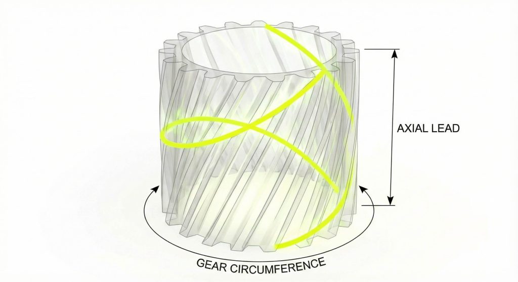
You calculate the angle by determining how far a tooth travels axially for one full rotation. This advanced metric for how to measure helix angle of helical gear is vital for understanding gear synchronization. You divide the pitch circumference by the lead to find the tangent of the helix angle.
What is the relationship between lead and angle?
You will find that a shorter axial lead results in a much steeper helix angle.
Look at it this way:
- Identify the number of teeth.
- Measure the lead over the full circumference.
- Apply the geometric conversion.
Key Takeaway: Understanding the relationship between lead and angle is essential for ensuring that mating gears synchronize without interference.
| Component | Variable | Influence |
|---|---|---|
| Axial Lead | Length | Determines slope steepness |
| Circumference | Pitch circle | Scale of rotation |
| Tangent | Angle | Resultant gear path |
You must use a specialized lead measurement tool for the most accurate results on small-pitch components.
How to measure helix angle of helical gear from photos?
You take high-resolution top-down photos and analyze them using computer-aided design software. When figuring out how to measure helix angle of helical gear, photogrammetry allows for remote analysis without handling the part. You overlay digital protractors on the image to find the angle between the tooth and the axis.
How do you avoid photographic distortion?
You must align the camera lens perfectly parallel to the gear face to ensure the perspective is flat.
Wait, there is more:
- Use a macro lens for detail.
- Import the file into CAD software.
- Trace the tooth center line.
Key Takeaway: Digital photo analysis is an excellent tool for consulting with remote engineers or documenting parts before disassembly.
| Method | Accuracy | Software |
|---|---|---|
| CAD Overlay | High | Drafting programs |
| Digital Ruler | Medium | Image analysis tools |
| Manual On-Screen | Low | Basic photo editors |
You should include a reference ruler in the photo to help calibrate the software’s scale accurately.
How to measure helix angle of helical gear with digital calipers?
You use digital calipers to measure the transverse and normal pitch of the gear teeth. This method for how to measure helix angle of helical gear relies on the difference between the tooth thickness measured at different planes. The cosine of the angle is the ratio of the normal pitch to the transverse pitch.
Why measure both pitch types?
You need both values because the helix angle causes the teeth to appear wider on the transverse plane.
Here is the kicker:
- Measure pitch perpendicular to the teeth.
- Measure pitch parallel to the gear face.
- Solve for the cosine angle.
Key Takeaway: Caliper-based pitch measurements allow you to derive the helix angle without needing to measure the angle directly.
| Pitch Type | Direction | Value Used For |
|---|---|---|
| Normal Pitch | Perpendicular | Real tooth thickness |
| Transverse Pitch | Parallel | Apparent thickness |
| Cosine | Ratio | Final angle calculation |
You must ensure the caliper jaws are clean and sharp to get into the root of the gear teeth.
How to measure helix angle of helical gear for replacements?
You must compare your findings with standard manufacturer angles to ensure the new part meshes correctly. Determining how to measure helix angle of helical gear often reveals that gears are cut at common intervals like 15 or 30 degrees. You should verify if the gear is a left-hand or right-hand helix before ordering a replacement.
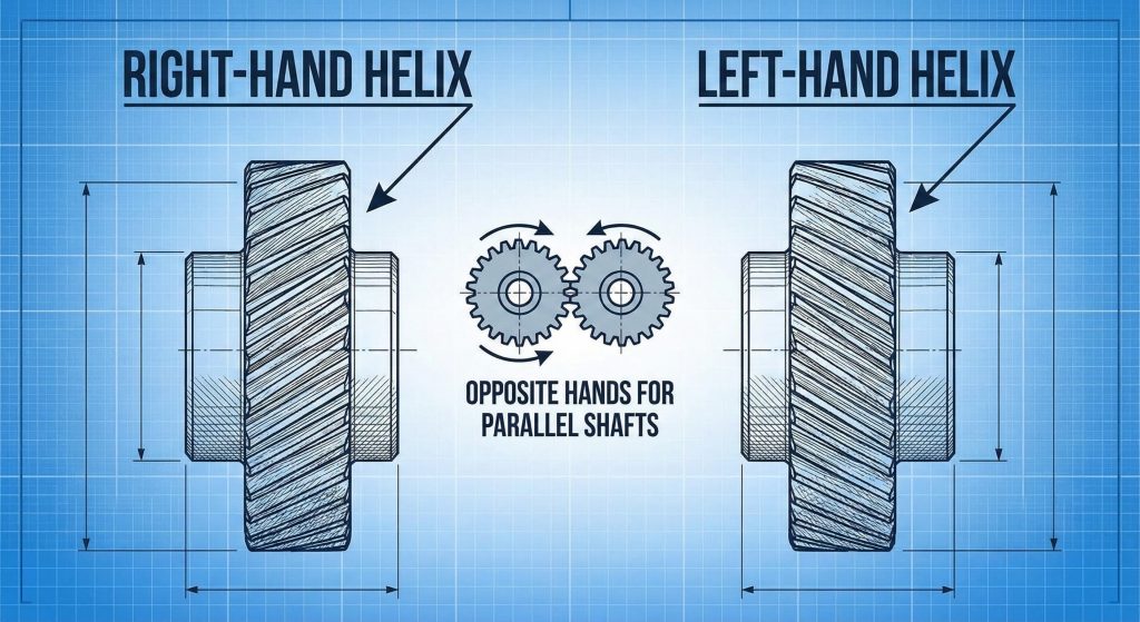
How do you identify the helix hand?
You look at the direction the teeth slope when the gear is placed on its flat face.
Think about it:
- Slope to the right is a right-hand helix.
- Slope to the left is a left-hand helix.
- Mating parallel gears must have opposite hands.
Key Takeaway: Identifying the “hand” of the gear is just as important as the angle itself for proper mechanical assembly.
| Hand | Direction | Mating Pair Rule |
|---|---|---|
| Right-Hand | Leans Right | Needs Left-Hand mate |
| Left-Hand | Leans Left | Needs Right-Hand mate |
| Crossed Axis | Both same | For non-parallel shafts |
You should check for part numbers on the gear hub which may encode the helix angle and hand directly.
How to measure helix angle of helical gear in lab settings?
You use coordinate measuring machines to verify the lead and profile of the gear in a laboratory setting. In professional manufacturing, how to measure helix angle of helical gear requires automated probes that map the tooth surface. This ensures the component meets strict quality standards for high-load applications.
Why is lab verification necessary?
You get sub-micron accuracy that manual tools simply cannot provide for high-speed transmission systems.
The bottom line:
- Automated probes detect pitch errors.
- Software generates a lead deviation chart.
- Reports confirm the exact helix angle.
Key Takeaway: Laboratory measurement is the only way to guarantee the precision required for heavy-duty industrial or aerospace gearsets.
| Feature | Lab Analysis | Manual Measurement |
|---|---|---|
| Precision | Sub-micron | Millimeter fractions |
| Documentation | Full traceability | User notes |
| Certification | Compliant reports | None |
You should seek professional lab services if the gear operates in a high-speed environment where noise and heat are critical factors.
Conclusion
Accurately measuring gear angles is the foundation of successful mechanical repair and maintenance. We have explored everything from manual paper traces to high-precision laboratory verification to solve the problem of missing documentation. Our vision is to provide every technician with the stability and quality data they need for long-term equipment reliability. If you need assistance with custom gear manufacturing or reverse engineering, contact us today to speak with an engineer.
Frequently Asked Questions
Can I measure a gear angle using a standard office ruler?
No, you need a tool that can measure the axial offset or a protractor that aligns with the tooth slope for accurate results.
What’s the best method for measuring the helix angle on a very small gear?
The best way is to use high-resolution photography and CAD software, as manual protractors are often too bulky for small teeth.
How do I know if my gear has a left-hand or right-hand helix?
If the teeth lean toward the right when the gear is upright, it is right-handed; if they lean left, it is left-handed.
Can I use a smartphone app for precision gear cutting?
No, phone apps are best for quick field estimates and should be verified with calipers or 3D printed test segments before machining.
How do I know if the measured angle is standard?
Most industrial gears use standard helix angles like 15, 20, or 30 degrees, so check if your measurement is close to these common values.