Introduction
Motion control systems often face a critical engineering contradiction: the need for massive torque reduction within an extremely limited physical footprint. You likely encounter scenarios where standard planetary or spur gearboxes are simply too bulky to fit into compact conveyor drives or packaging machinery, yet you cannot sacrifice output power or positional stability.
Here is the brutal truth: ignoring these spatial and efficiency constraints does more than just complicate your design; it actively eats into your operational budget through frequent maintenance cycles and unexpected failures. When a generic gearbox fails due to poor thermal management or untraceable material quality, the resulting downtime can cost thousands of dollars per hour in lost production, not to mention the reputational damage when your equipment fails at a customer site.
The worm gear remains the premier engineering solution for achieving high reduction ratios and self-locking capabilities in tight spaces. This guide provides a comprehensive technical breakdown of worm drive mechanics, material specifications, and selection criteria to ensure you choose a component that lasts. At Yantong Tech, we specialize in manufacturing high-precision worm gears that come with full metallurgical traceability and ISO-grade accuracy, ensuring your machinery runs smoothly without the risk of “fit-and-forget” component failure.
1. History and Evolution of Worm Gearing
From Ancient Mechanics to Modern CNC
The worm drive has evolved from Archimedes’ early designs for lifting water into a cornerstone of modern industrial power transmission, shifting from rough sand-casting methods to ultra-precision CNC manufacturing. Today, the focus has moved entirely toward maximizing efficiency and surface finish through advanced processes like hard skiving and honing, which dramatically reduce friction compared to traditional cutting methods. But the story doesn’t end there…
- Early worm gears relied on simple iron-on-iron contact, which limited load capacity and generated excessive heat.
- The Industrial Revolution introduced the critical specialized pairing of hardened steel worms with softer bronze wheels to manage tribological stress.
- Modern CNC hobbing at facilities like Yantong Tech allows for micron-level modifications to the tooth profile, optimizing the contact patch for heavy loads.
The Role of Material Science in Gear Evolution
The most significant leap in worm gear technology was not geometric but metallurgical, specifically the discovery that dissimilar metals are required to prevent galling during sliding contact. Engineers realized that a hardened steel shaft interacting with a phosphor bronze wheel provided the ideal balance of durability and lubricity, a standard that defines reliable gearing today.
- Case-hardening the steel worm (often 20CrMnTi) creates a wear-resistant surface while maintaining a tough, ductile core to absorb shock loads.
- Centrifugally cast bronze wheels offer a denser grain structure than sand-cast alternatives, significantly improving fatigue resistance.
- Advanced nitriding processes are now employed to further reduce surface friction coefficients without making the material brittle.
Key Takeaway
Understanding the historical shift toward precision metallurgy helps you appreciate why modern manufacturing tolerances (ISO 6-7) are non-negotiable. You cannot achieve long-term efficiency with outdated material pairings or loose machining standards; precision is the only path to reliability.
2. Basic Components and Mechanics
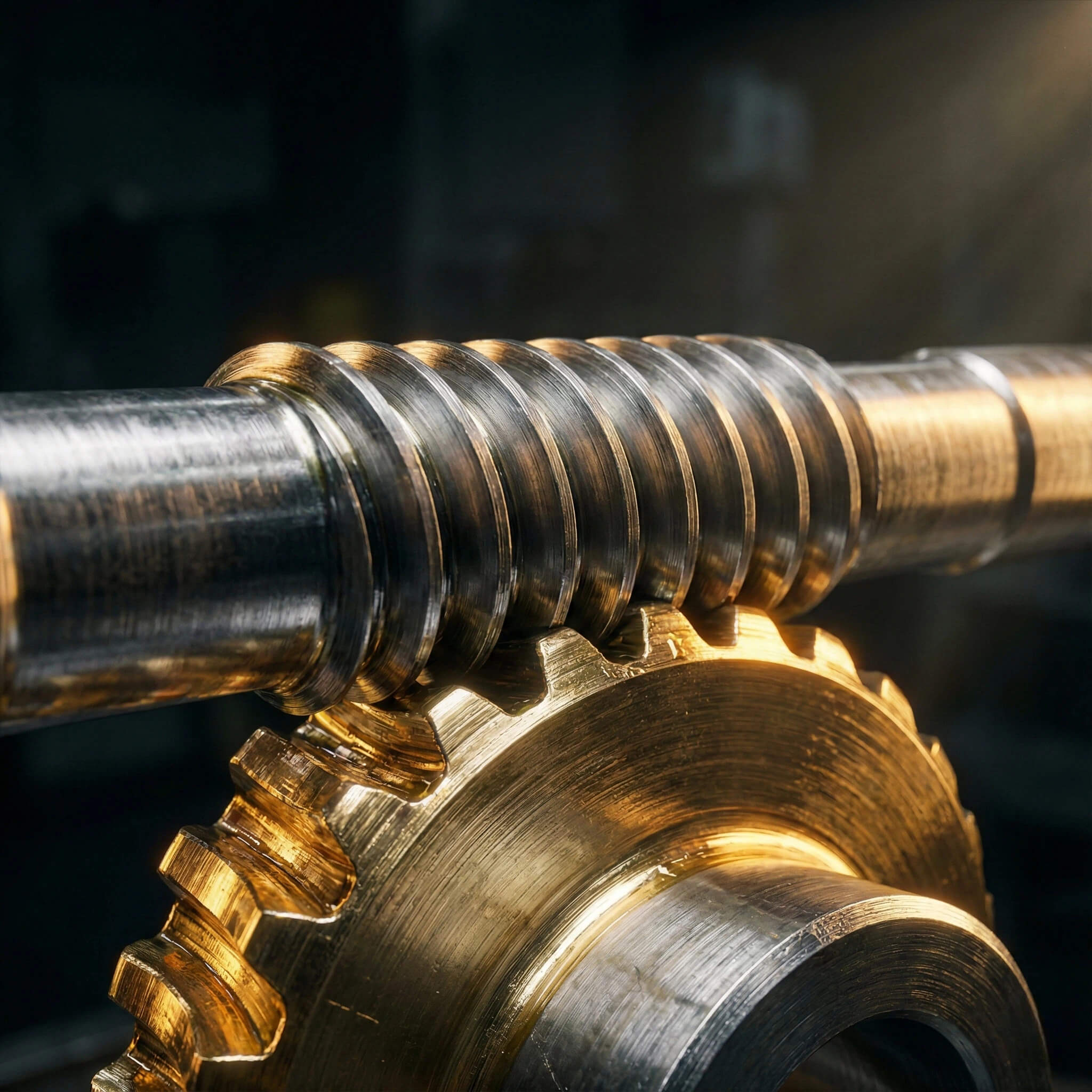
The Anatomy of a Worm Drive
A worm drive consists of two primary mating components: the worm (a screw-like shaft) and the worm wheel (a helical gear), which operate on non-intersecting, perpendicular axes. The worm is almost invariably manufactured from high-strength alloy steel to withstand the input torque, while the wheel uses a softer alloy to function as a sacrificial wear surface.
- The worm acts as the driving element, with its spiral thread engaging multiple teeth on the wheel simultaneously to distribute load.
- The wheel is typically concave (throated) to wrap around the worm, maximizing the contact area and increasing torque transmission capabilities.
- Shaft orientation is fixed at 90 degrees, allowing for compact right-angle power transmission that simplifies drivetrain layouts.
How Does a Worm Gear Achieve High Torque?
Unlike spur gears that rely on rolling contact, worm gears function primarily through sliding action, which allows for massive reduction ratios in a single stage. The reduction ratio is calculated simply by dividing the number of teeth on the gear by the number of threads (starts) on the worm, enabling reductions of 60:1 or higher in a box the size of a shoebox. You might be wondering…
- Sliding contact generates a “wedge” effect, multiplying torque significantly more than leverage-based rolling gears.
- Single-start worms offer the highest reduction ratios and self-locking potential but generate the most friction.
- Multi-start worms increase efficiency and speed but sacrifice some of the self-locking properties inherent to the design.
Key Takeaway
A worm gear is not just a standard cog; it is a complex sliding friction system that demands precise material pairing. If you treat it like a standard rolling gear, you will likely overlook the critical lubrication and thermal management requirements necessary to prevent rapid failure.
3. Understanding Worm Gear Specifications
Decoding Lead Angle and Pitch Diameter
The lead angle—the angle between the helix of the thread and the plane of rotation—is the single most critical geometric factor determining the efficiency and reversibility of your worm gear set. A shallow lead angle promotes self-locking behavior but increases friction, while a steep angle improves efficiency at the cost of holding capability.
- Low lead angles (under 5 degrees) typically result in self-locking gears that cannot be back-driven by the load.
- Pitch diameter directly correlates to the torque capacity; a larger pitch diameter allows for a more robust tooth root.
- Designers must balance the lead angle against the input speed to avoid excessive sliding velocities that shear oil films.
Material Standards and Heat Treatment
Selecting the correct materials is far more important than geometry alone; industry standards typically dictate a case-hardened alloy steel worm paired with a specific grade of phosphor or aluminum bronze. At Yantong Tech, we provide comprehensive heat treatment reports for every batch, verifying that the case depth and surface hardness meet the rigorous demands of industrial operation.
- Common steel grades like SAE 8620 or 20CrMnTi are carburized to HRC 58-62 to resist abrasive wear from the bronze wheel.
- The bronze wheel material (e.g., CuSn12Ni2) must be chemically verified to ensure it has the correct tin content for lubricity.
- Heat treatment reports are not optional paperwork; they are your only proof that the gear will not fail prematurely under load.
Accuracy Classes (ISO vs. AGMA)
Accuracy classes, such as ISO 1328 Grade 6 or 7, define the allowable errors in tooth profile, lead, and pitch, which directly impact vibration and noise levels during operation. A high-precision gear ensures that the contact pattern is centered and consistent, preventing localized hot spots that lead to pitting and failure. Here is why this matters:
- Grade 6 gears are ground to precise tolerances, making them suitable for high-speed or low-noise applications like medical devices.
- Lower accuracy grades (8-10) may be acceptable for slow agricultural machinery but will be noisy and run hot in automation contexts.
- Consistent manufacturing tolerances ensure that replacement parts fit perfectly without requiring extensive run-in periods.
Specification Comparison
| Material / Parameter | Common Standard | Hardness / Characteristic | Typical Application |
|---|---|---|---|
| Worm Shaft | 20CrMnTi / SAE 8620 | HRC 58-62 (Case Hardened) | General Industrial Power Transmission |
| Worm Shaft (Heavy) | 18CrNiMo7-6 | HRC 58-62 (Deep Case) | Heavy Mining & Construction |
| Worm Wheel (Standard) | CuSn12 (Phosphor Bronze) | HB 90-120 (Low Friction) | Conveyors, Packaging, Lifts |
| Worm Wheel (High Load) | CuAl10Ni (Al-Bronze) | HB 150-180 (High Strength) | Heavy Winches (Requires periodic lube) |
| Accuracy Class | ISO Grade 6-7 | Ground & Honed Profile | Precision Servo Drives |
Expert Analysis: As experts at Yantong Tech, we recommend prioritizing material certification over geometry; a perfect shape with the wrong alloy will fail in weeks, whereas a certified material pairing ensures years of reliable service.
Key Takeaway
Do not just order a worm gear by its physical dimensions; you must specify the material certification and accuracy grade. This ensures that the components you receive are interchangeable, traceable, and capable of surviving the thermal and mechanical stresses of your specific application.
4. Advantages and Real-World Limitations
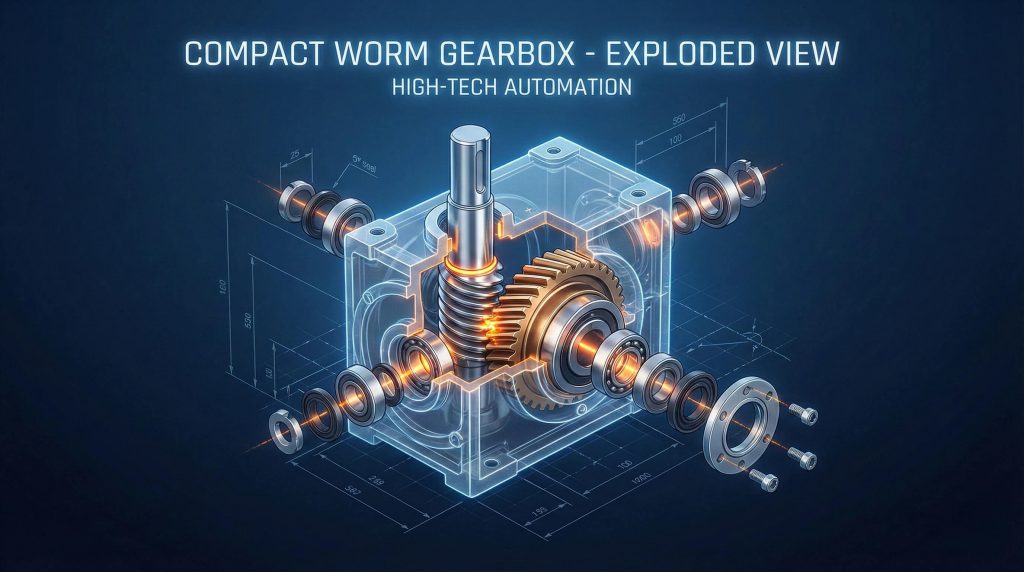
The Power of Self-Locking and Compactness
The primary advantage of the worm gear is its inherent ability to prevent back-driving, meaning the output shaft cannot rotate the input shaft under load, acting as a passive brake. This feature, combined with the ability to achieve reduction ratios of 60:1 or 100:1 in a single stage, makes it indispensable for applications where space is at a premium and safety is paramount.
- Self-locking is ideal for hoisting equipment where gravity might otherwise cause a load to fall if power is lost.
- The right-angle configuration allows motors to be mounted parallel to the machine frame, saving valuable aisle space in factories.
- Fewer moving parts compared to multi-stage spur gearboxes result in lower initial costs and simplified maintenance routines.
The Efficiency Trade-Off (Heat Generation)
The sliding action that gives worm gears their high torque and quiet operation comes at a thermodynamic cost: significant energy is lost as heat due to friction at the tooth interface. Efficiency drops dramatically as the reduction ratio increases, meaning high-ratio boxes require careful thermal monitoring and often larger motors to compensate for the power loss. Let’s be honest for a second…
- Efficiencies can range from 90% for low ratios down to 50% for very high ratios, necessitating cooling fins or fans.
- The generated heat can degrade lubricant viscosity, leading to a vicious cycle of increased friction and further overheating.
- Designers must factor in a “thermal service factor” to ensure the gearbox housing can dissipate the heat generated during continuous duty.
Comparison of Gear Types
| Feature | Worm Gear | Planetary Gear | Bevel Gear |
|---|---|---|---|
| Reduction Ratio | High (5:1 to 100:1 per stage) | Medium (3:1 to 10:1 per stage) | Low (1:1 to 5:1) |
| Efficiency | Low to Medium (50-90%) | High (95%+) | High (95-98%) |
| Back-Driving | Self-Locking (Ratio dependent) | Reversible | Reversible |
| Noise Level | Low (Sliding contact) | Medium | Medium to High |
| Space Footprint | Compact (Right Angle) | Compact (Inline) | Bulky (Right Angle) |
Expert Analysis: While efficiency is lower, the utility of high-ratio reduction in a single stage often outweighs the energy loss in intermittent applications where holding position is more critical than energy conservation.
Key Takeaway
Worm gears are the undisputed champions of “high ratio, low space” engineering. However, you must accept and manage the thermal trade-offs; if your application runs continuously at high speeds, you need to verify the thermal capacity of the housing, not just the mechanical strength of the teeth.
5. Common Applications Across Industries
Heavy Machinery and Material Handling
In the heavy machinery sector, worm gears are ubiquitous in conveyor drives, rock crushers, and mining hoists where stopping a heavy load safely is non-negotiable. The natural braking effect provides a layer of safety that reduces reliance on external braking systems, although it should never replace a primary safety brake in critical lifting operations.
- Used extensively in apron feeders and belt conveyors to prevent rollback when the power is cut.
- Yantong Tech supplies robust, large-module worm sets specifically designed to withstand the shock loads of mining environments.
- Their compact nature allows high-torque drives to be retrofitted into existing tight spaces on mobile construction equipment.
Precision Automation and Packaging
Beyond brute force, worm gears are essential in packaging machinery, rotary indexing tables, and filling lines where smooth motion and low noise are required. The sliding contact dampens vibration, resulting in a “silent running” capability that is crucial for machines operating in close proximity to human workers or sensitive electronics. Think about it this way:
- In pharmaceutical dosing machines, the lack of vibration ensures precise fill weights and prevents product settling.
- Zero-backlash or low-backlash duplex worm gears are used in precision positioning stages to eliminate play.
- Food-grade environments often utilize stainless steel worms with specialized bronze wheels to withstand washdown procedures.
Application Suitability Matrix
| Industry | Application | Key Requirement | Recommended Gear Type |
|---|---|---|---|
| Mining | Conveyor Drives | Anti-Rollback / High Torque | Heavy Duty Steel/Bronze Worm |
| Logistics | Sorting Systems | Compact Size / Right Angle | Standard Shell Cast Worm Box |
| Packaging | Rotary Indexing | Low Vibration / Precision | Ground Profile Low-Backlash Worm |
| Construction | Crane Hoists | Self-Locking Safety | Single-Start High-Ratio Worm |
| Food & Bev | Mixing Tanks | Washdown / Hygiene | Stainless Steel / Sealed Unit |
Expert Analysis: Applications that require safety brakes often benefit naturally from the worm gear’s inherent resistance to reversing, adding a redundant layer of safety that simpler gear trains cannot provide.
Key Takeaway
Whether you are designing a heavy-duty crane or a delicate food packaging line, the application defines the gear. You must communicate the duty cycle and precision requirements to your manufacturer, as a mining gear will destroy a packaging machine, and a precision gear will shatter in a rock crusher.
6. Selection Guide: Choosing the Right Gear
How to Calculate the Correct Ratio and Service Factor
Selecting the right worm gear begins with calculating the required reduction ratio (Input Speed / Output Speed) and applying the correct Service Factor (S.F.) based on the operational duty cycle. Many engineers make the mistake of selecting a gearbox based solely on nominal motor power, ignoring the fact that frequent starts/stops or shock loads can effectively double the torque requirement.
- Always calculate torque demand at the output shaft, not just the motor rating, to account for efficiency losses.
- A Service Factor of 1.0 is for uniform load, 8 hours/day; heavy shock loads or 24/7 operation may require an S.F. of 1.5 or 2.0.
- Ignoring the S.F. is the primary cause of sheared teeth and overheated gearboxes in the first month of operation.
Why Sourcing Strategy and Traceability Matter
The sourcing strategy you employ is just as critical as the engineering design; buying gears from suppliers who cannot provide CMM reports or material certificates is a gamble with your company’s reputation. A reliable partner like Yantong Tech engages in “Engineer-to-Engineer” communication, ensuring that the manufacturing process aligns perfectly with your design intent and risk profile. It gets better:
- Traceability allows you to pinpoint the exact batch of raw material in case of a field failure, limiting liability.
- A supplier that understands your application can suggest subtle tooth modifications (crowning) to improve load distribution.
- Transparent quoting based on actual manufacturing risks rather than low-ball estimates prevents surprise costs later.
Key Takeaway
A reliable gear starts with a reliable print and a partner who can read it. Always verify that your supplier has the capability to interpret, validate, and certify your engineering drawings, ensuring that what you design is exactly what allows your machine to move.
7. Maintenance Tips for Longevity
The Critical Role of Lubrication
Lubrication is the lifeblood of a worm gear; because the system operates in a regime of sliding friction, the oil film must withstand significant shearing forces that would tear apart standard gear oils. Using the wrong viscosity or type of oil is the single fastest way to destroy a worm gear set, leading to rapid bronze wear and catastrophic overheating.
- Synthetic oils (PAG or PAO based) are highly recommended for their thermal stability and longer change intervals.
- Extreme Pressure (EP) additives are necessary to protect the bronze wheel from scoring under heavy shock loads.
- The oil level must be strictly maintained; too little causes starvation, while too much causes churning and foaming heat.
Inspecting for Wear: The “Contact Pattern”
Regular inspection of the “contact pattern” on the bronze wheel teeth provides a clear diagnostic window into the health of your gearbox. A centered, oval-shaped wear pattern indicates healthy alignment and load distribution, while offset patterns suggest shaft misalignment or bearing wear that needs immediate attention. Bottom line?
- Pitting or spalling on the bronze teeth indicates surface fatigue, likely due to overloading or oil degradation.
- Scoring lines (vertical scratches) suggest the presence of particulate contamination in the oil or lubrication failure.
- Discoloration of the worm shaft (blueing) is a sure sign of extreme overheating, necessitating an immediate review of cooling and load.
Preventative Maintenance Checklist
| Interval | Action Item | What to Look For |
|---|---|---|
| Daily | Visual & Thermal Check | Oil leaks, excessive noise, housing temperature >80°C |
| Monthly | Oil Analysis | Darkening oil (oxidation), metallic particles (bronze dust) |
| 6 Months | Alignment Check | Loose mounting bolts, coupling misalignment |
| Yearly | Full Inspection | Draining oil, inspecting gear teeth for pitting/wear pattern |
| 2500 Hrs | Oil Change | Replace mineral oil (extend to 5000 hrs for synthetic) |
Expert Analysis: 90% of worm gear failures are lubrication-related; using the wrong oil or neglecting change intervals is an expensive mistake that is entirely preventable with a basic maintenance schedule.
Key Takeaway
Maintenance is not just about fixing things when they break; it is about monitoring thermal stability and oil quality to extend the Lifecycle Cost (LCC) of the asset. A proactive lubrication strategy is the cheapest insurance policy you can buy for your drivetrain.
Conclusion
Worm gears remain the most effective solution for applications requiring high torque, compact reduction, and self-locking capabilities, provided their thermal characteristics are managed correctly. They solve the fundamental problem of fitting massive power into tight spaces, but they demand respect regarding lubrication and material quality.
At Yantong Tech, we don’t just cut metal; we provide peace of mind. From rigorous material heat treatment reports to final CMM inspection data, we ensure that every gear we ship is built to survive real-world industrial abuse. We believe in transparent manufacturing that lets you trace reliability back to the source.
Ready to stabilize your drive systems? Contact Yantong Tech today for a customized worm gear solution tailored to your needs.
FAQ
Q1: What’s the best worm gear for heavy machinery?
Double-enveloping worm gears or high-grade bronze pairings. Reason: Heavy machinery requires maximum surface contact to distribute load shock; standard cylindrical worms may wear prematurely under heavy vibration.
Q2: Can all worm gears self-lock?
No, it depends entirely on the lead angle. Reason: generally, only worm gears with a lead angle of less than 5 degrees (and high ratios) are truly self-locking. Relying on them for safety without a brake is a design risk.
Q3: How often should I change the oil in a worm gearbox?
Every 2,500 to 5,000 operating hours, depending on oil type. Reason: Synthetic oils last longer, but because worm gears generate significant sliding heat, the oil degrades faster than in spur gearboxes.
Q4: Why is my worm gear overheating?
It is likely due to excessive input speed or incorrect viscosity. Reason: High sliding velocity creates friction heat. If the oil film breaks down or the box is overfilled/underfilled, the unit cannot dissipate heat effectively.