INTRODUCTION
Designing a machine for high torque and compact space often leads engineers to the worm gear, but this choice frequently introduces a frustrating cycle where transmission temperatures spike, efficiency plummets, or components fail months before their rated lifespan. This is not merely a maintenance annoyance; unexpected gearbox failure kills production lines, skyrockets the Total Cost of Ownership (TCO), and damages your engineering reputation with clients who demand absolute reliability. When a critical drive fails, the downtime costs often dwarf the price of the component itself, leaving you scrambling to explain why the theoretical safety factor did not hold up in the real world.
This guide cuts through the theoretical noise to provide actionable design standards, material pairings, and manufacturing insights backed by Yantong Tech’s extensive experience in delivering high-precision worm gears to demanding markets like Germany and the USA. By focusing on the practical realities of sliding friction and thermal management, we will transform how you approach power transmission design to ensure your systems perform as robustly in operation as they do on paper.
ESSENTIALS OF WORM GEAR DESIGN GUIDE
What defines a worm gear system?
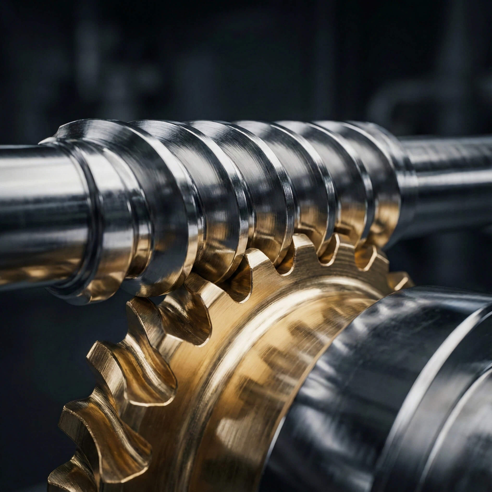
A worm gear set is unique because it transmits power between non-intersecting shafts, typically at 90 degrees, relying heavily on sliding contact rather than the rolling action found in other gears. This fundamental difference dictates every design choice you make, from lubrication to thermal management, as the sliding action generates significantly more heat than standard involute gearing.
- Worm (Input/Driver): The screw-like shaft that initiates motion and bears the brunt of the friction.
- Worm Wheel (Output/Driven): The gear that meshes with the worm, typically made of softer material.
- Housing and Bearings: Critical elements for maintaining precise alignment under heavy load.
Here is the deal: Understanding the sliding nature is the first step to preventing premature wear.
How does the reduction ratio work?
The gear ratio is determined by dividing the number of teeth on the worm wheel by the number of starts (threads) on the worm shaft. Unlike spur gears, you can achieve massive reductions (up to 100:1) in a single compact stage without complex trains, making them ideal for confined spaces.
- Single-start worm: Achieves the highest ratio but suffers from lower efficiency due to high friction.
- Multi-start worm: Provides a lower ratio but runs at much higher speeds and efficiency.
- Center distance constraints: Limits the physical size of the wheel relative to the worm shaft.
KEY TAKEAWAY
Prioritize the number of starts early in your design process because it strictly dictates your efficiency ceiling. If you select a single-start worm for a high-speed application, you are mathematically guaranteeing heat generation that no amount of cooling can fully resolve, so always balance your ratio needs with thermal realities.
CRITICAL WORM DRIVE COMPONENTS
What is the function of the worm shaft?
The worm acts as the screw that drives the system, handling high rotational speeds and significant friction during operation. It must be the harder component in the pair to maintain geometry under load and resist abrasive wear from the constant sliding action against the wheel.
- Thread profile: Typically Trapezoidal or Involute (ZI, ZK, ZN types) for optimal contact.
- Surface finish: Crucial for efficiency; must be ground to mirror quality to minimize friction.
- Shaft stiffness: Essential to prevent deflection that causes destructive edge loading.
You might be wondering: Why is the surface finish so critical?
Why is the worm wheel sacrificial?
The worm wheel is designed to conform to the worm’s harder surface, effectively bedding in during operation to increase the contact patch. By making the wheel softer, you ensure that wear is concentrated on the easier-to-replace component, protecting the precision-ground worm shaft from damage.
- Conformability: Adapts to minor misalignments during the break-in period.
- Embeddability: Absorbs foreign particles to prevent scoring of the harder shaft.
- Low friction coefficient: Essential for maintaining a viable sliding contact interface.
KEY TAKEAWAY
Design the system so the cheapest part, usually the wheel ring, fails first to save the expensive shaft and minimize repair costs. This sacrificial design philosophy is the bedrock of economical maintenance strategies in heavy industry, allowing for quick ring replacements rather than full gearbox overhauls.
CALCULATING GEAR EFFICIENCY & TORQUE
How do you calculate real efficiency?
Efficiency is not a fixed number; it fluctuates based on the lead angle and the coefficient of friction during actual operation. A simple formula considers the tangent of the lead angle against the friction angle, but real-world efficiency drops significantly as heat breaks down the oil film and increases metal-to-metal contact.
- Lead angle magnitude: Larger angles generally increase efficiency by reducing sliding.
- Sliding velocity: Higher speeds can improve hydrodynamic film formation up to a thermal limit.
- Lubricant viscosity: Thicker oil creates drag but protects better against surface wear.
But here is the kicker: High reduction ratios often yield efficiencies as low as 40-50%.
What determines self-locking capability?
Self-locking occurs when the friction angle between the teeth is greater than the lead angle of the worm, typically requiring a lead angle of less than 5 degrees. This prevents the output load from back-driving the input, a critical safety feature for hoists and elevators, though it is not absolute.
- Lead angle: Must be strictly less than 5 degrees for static self-locking.
- Static friction coefficient: Varies with oil type, temperature, and surface finish.
- External vibration: Can momentarily break friction, causing unexpected creep.
CALCULATION SUMMARY TABLE
| Metric | Key Factor | Implication |
|---|---|---|
| Efficiency Calculation | Lead Angle vs. Friction Angle | Single-start worms sacrifice 50% energy for high torque. |
| Self-Locking Threshold | Lead Angle < 5 Degrees | Cannot rely on this for safety-critical holding. |
| Torque Output | Wheel Pitch Diameter | Larger wheels provide greater leverage and load capacity. |
EXPERT ANALYSIS
Yantong Tech engineers warn that efficiency tables in catalogs are based on ideal running conditions; you must apply a safety factor of 0.85 to these figures when designing for start-up conditions where static friction is significantly higher.
KEY TAKEAWAY
Never rely solely on self-locking for critical safety; always use a secondary brake for load holding. The self-locking property is dynamic and can fail under vibration or with highly polished, well-lubricated surfaces, making a mechanical brake mandatory for vertical lifting applications.
MATERIAL SELECTION FOR DURABILITY
Why use differential hardness?
The “Golden Rule” of worm gearing is pairing materials with significantly different hardness levels to prevent galling or cold welding. You typically pair a case-hardened steel worm (58-62 HRC) with a softer bronze wheel to manage the extreme sliding friction without seizing.
- Worm Standard: 20CrMnTi or 42CrMo4 (Carburized and Hardened).
- Wheel Standard: CuSn10P1 Phosphor Bronze (Centrifugally cast).
- Alternative: Aluminum Bronze or Nickel Bronze for extreme loads.
This is where it gets interesting: The bronze must be tough enough to carry the load but soft enough to not score the steel.
When should you choose aluminum bronze?
While Phosphor Bronze is the standard for lubricity, Aluminum Bronze offers superior strength and corrosion resistance for harsh environments. However, it is harder and less forgiving, requiring a worm shaft with exceptional surface hardness and finish to prevent rapid wear of the worm itself.
- Heavy shock loads: Ideal for mining and crushing equipment.
- Marine environments: Resists corrosion in winches and offshore actuators.
- Low-speed drives: Best where sliding velocity is manageable but torque is high.
MATERIAL PAIRING SUMMARY TABLE
| Component | Standard | Application |
|---|---|---|
| Worm Shaft | 20CrMnTi / 42CrMo4 | High speed, continuous duty, precision drives. |
| Worm Wheel (Standard) | Phosphor Bronze (CuSn10P1) | General industrial, high efficiency, high sliding speeds. |
| Worm Wheel (Heavy Duty) | Aluminum Bronze (CuAl10Ni) | Heavy shock loads, intermittent duty, corrosive environments. |
| Worm Wheel (Economy) | Cast Iron (FC200) | Low cost, low speed, manual drives, non-critical usage. |
EXPERT ANALYSIS
Selecting materials is about matching the microstructure to the duty cycle; Yantong Tech emphasizes that if you switch to Aluminum Bronze for strength, you must simultaneously upgrade your lubrication and minimize the worm’s surface roughness (Ra) to prevent it from acting like a file.
KEY TAKEAWAY
Match the material not just to the load, but to the operating speed and maintenance capabilities of your end user. While stronger materials like Aluminum Bronze seem superior, they lack the natural lubricity of Phosphor Bronze and can lead to catastrophic failure if lubrication regimes are not strictly followed.
PRECISION MANUFACTURING STANDARDS
Why is precision grinding non-negotiable?
Hobbing alone leaves microscopic “scallops” on the gear flank that act like sandpaper in a sliding contact worm drive. Yantong Tech employs precision thread grinding after heat treatment to remove distortions and achieve a mirror-like finish (Ra < 0.4), drastically reducing heat generation.
- Corrects distortion: Ensures perfect geometry after heat treatment.
- Reduces noise (NVH): Smoother engagement limits vibration and operating sound.
- Increases efficiency: Can improve throughput by 10-15% by reducing friction.
Ready for the good part? Grinding transforms a standard gear into a high-performance component.
How do we control backlash effectively?
Backlash is the clearance required for lubrication but detrimental to precision positioning in automation. It is controlled through precise center distance machining and tooth thickness modification during the manufacturing stage, or by using dual-lead (duplex) worms for adjustable backlash.
- Class 6 ISO tolerances: Tight manufacturing standards for minimal play.
- Adjustable center distance: Allows mechanical adjustment of the housing.
- Duplex worm design: Variable pitch allows wear compensation over time.
KEY TAKEAWAY
Specify the exact backlash you need; too tight creates excessive heat, while too loose reduces accuracy and introduces shock loading. “Zero backlash” is physically impossible without high friction, so always engineer a tolerance that permits a vital oil film to exist between mating surfaces.
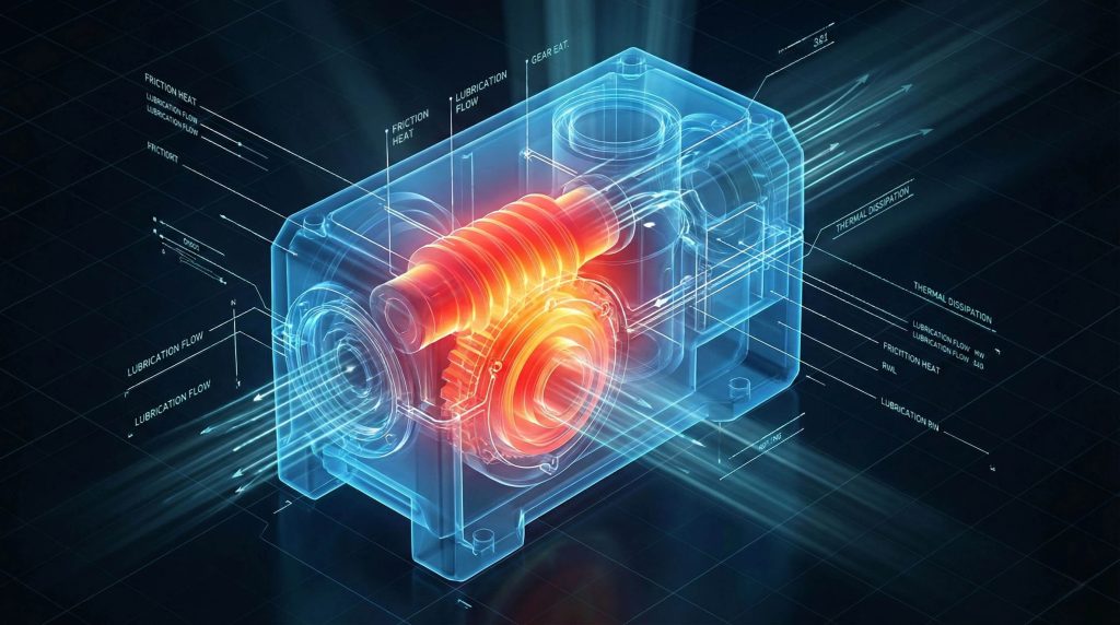
OPTIMIZING THERMAL PERFORMANCE
What causes pitting and scoring?
Pitting is surface fatigue caused by overloading the bronze wheel, while scoring is severe adhesive wear caused by lubrication failure. Both are signs that the contact stress or thermal limits of the material pair have been exceeded during operation.
- Small craters: Pitting on tooth flanks indicating mechanical overload.
- Vertical gouges: Scoring marks indicating breakdown of the lubricant film.
- Discolored oil: Signs of oxidation and overheating within the sump.
What’s the real story? Most gear failures are actually lubrication failures in disguise.
How do you manage thermal overload?
Worm gears are heat generators due to sliding friction, and the gearbox housing must effectively dissipate this energy to prevent failure. If the thermal rating is exceeded, the oil thins, the seal fails, and the gears destruct; often requiring cooling fins, fans, or synthetic oil to manage.
- Finned housings: Increase surface area for natural convection.
- Shaft-mounted fans: Provide forced air cooling to the casing.
- PAG Synthetic oils: Significantly lower internal friction and operating temperature.
TROUBLESHOOTING SUMMARY TABLE
| Failure Mode | Visual Indicator | Practical Solution |
|---|---|---|
| Pitting | Craters on bronze teeth | Increase wheel size (module) or switch to Al-Bronze. |
| Scoring | Vertical scratches/welding | Switch to PAG oil (ISO 460/680) or reduce input speed. |
| Overheating | Paint peeling / Burnt oil | Improve worm surface finish (Grind) or add cooling fans. |
| Tooth Fracture | Broken tooth at root | Upsize module or use soft-start drive mechanics. |
EXPERT ANALYSIS
The distinction between Mechanical Rating and Thermal Rating is vital; Yantong Tech engineers often solve failures not by upsizing the gears, but by improving the thermal path through synthetic lubrication and precision grinding to reduce the heat source at its origin.
KEY TAKEAWAY
Always check the Thermal Rating of a gearbox, not just the Mechanical Rating, as it is usually the limiting factor. A gearbox mechanically capable of handling a load may still fail if it cannot dissipate the heat generated, leading to seal burnout and subsequent catastrophic gear seizure.
BEST PRACTICES FOR INSTALLATION
How to optimize lubrication strategies?
Never use standard hydraulic oil; worm gears require oils with high film strength and low coefficients of friction to survive. Polyglycol (PAG) synthetic oils are the gold standard, offering excellent thermal stability and efficiency improvements compared to mineral oils.
- Viscosity: Use ISO VG 460 or 680 for low speeds and high loads.
- Compatibility: Check compatibility with seals (Viton vs NBR) to prevent leaks.
- Maintenance: Schedule regular oil analysis to detect bronze particles early.
Here is the bottom line: The right oil is the cheapest insurance you can buy.
Why is alignment the silent killer?
Even the best-manufactured gears will fail if the worm is not centered exactly over the wheel’s pitch circle during assembly. Misalignment concentrates the load on the tooth edges, halving the load capacity and accelerating wear instantly.
- Contact pattern verification: Use Prussian Blue to check meshing area.
- Bearing preload settings: Ensure rigidity without binding the shaft.
- Housing rigidity: Prevent flexing under peak load to maintain alignment.
KEY TAKEAWAY
Always verify the contact pattern under light load before full operation using a marking compound. A centered contact pattern is the only proof that your theoretical design has been translated into a functional reality, ensuring the load is distributed evenly across the gear face.
CONCLUSION
Designing a successful worm gear drive is a balancing act between torque requirements and thermal limitations. The problems of inefficiency and premature failure are solved not just by better math, but by better manufacturing—specifically, the differential hardness of materials and the surface finish achieved through precision grinding. The difference between a gearbox that lasts six months and one that lasts six years often comes down to the microscopic details: the Ra value of the worm flank, the precise chemistry of the bronze, and the viscosity of the oil film.
Yantong Tech provides the engineering partnership you need, offering fully traceable, precision-ground worm gears that meet rigorous ISO standards. We do not just sell you a gear; we sell you the peace of mind that comes from a component engineered to last. By combining our advanced manufacturing capabilities with your specific application needs, we drive innovation that keeps your machinery running longer and cooler.
Contact Yantong Tech today for tailored worm gear consultations and secure your production reliability.
FAQ
Can I rely on my worm gear design to self-lock for safety?
No, you should never rely solely on worm gearing for safety-critical braking. External vibrations, surface polishing over time, or using high-efficiency synthetic oils can lower friction enough to cause back-driving, necessitating a fail-safe mechanical brake.
What is the best material for high-load worm gear applications?
The best combination is a Case-Hardened Alloy Steel Worm paired with an Aluminum Bronze Wheel. This pairing offers the highest resistance to surface fatigue and shock loading, provided that lubrication is strictly maintained to handle the increased hardness.
How do I know if my efficiency calculations are accurate?
Real-world efficiency is likely lower than theoretical values due to thermal breakdown and imperfect lubrication. Expect efficiencies to range between 50% for single-start, high-ratio drives and 90% for multi-start, low-ratio drives, dependent heavily on sliding speed.
What is the best way to stop my worm gear from overheating?
Switch to a high-viscosity PAG synthetic gear oil immediately. Overheating is usually caused by excessive sliding friction, and synthetic oils significantly reduce internal friction and improve thermal stability compared to mineral oils.
How do I choose between single-start and multi-start worms?
Choose single-start for high reduction ratios in compact spaces where efficiency is secondary. Choose multi-start worms for applications requiring higher speeds and efficiency, as they generate significantly less heat due to a larger lead angle.