
In complex mechanical systems, engineers often struggle with fitting high-torque transmission into tight, restrictive spaces using standard gear sets. Relying on bulky spur gears or multiple reduction stages increases weight, costs, and the risk of mechanical failure due to complexity and inefficiency. Worm gearing offers a streamlined solution, providing massive speed reduction and reliable torque in a single, compact stage, as detailed in this guide.
Basics of Worm and Worm Gear Formulas
What Defines a Worm Drive System?
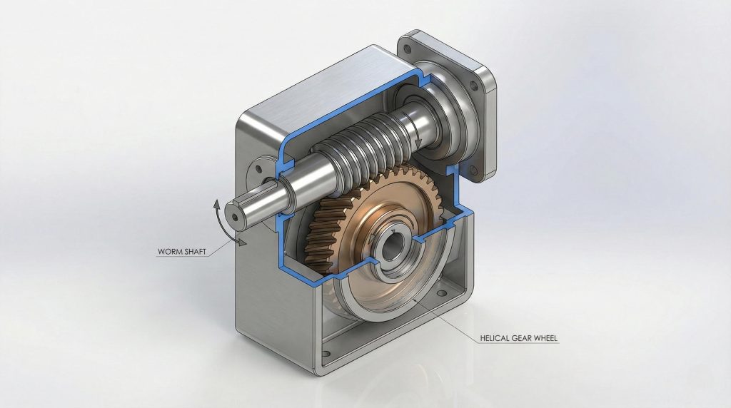
Ideally, you want to know exactly what components are interacting inside the gearbox to predict performance. A worm drive consists of a worm (a screw-like shaft) driving a worm wheel (a helical-toothed gear), typically arranged with non-intersecting shafts at a 90-degree angle.
- Worm: The driving input, resembling a screw thread.
- Worm Wheel: The driven output, resembling a spur gear with curved teeth.
- Shaft Angle: Almost exclusively 90 degrees (perpendicular).
Why Choose This Unique Gearing?
You might choose this system because the sliding action between the worm and wheel results in significantly quieter operation than the rolling impact of spur gears.
Here is the best part:
- High Reduction: Achieve ratios up to 100:1 in a single stage.
- Compact Design: Fits high torque capacity into a small housing.
- Smooth Operation: Continuous sliding contact reduces vibration and noise.
How Do Materials Affect Formulas?
To prevent the system from seizing due to high friction heat, you must pair dissimilar materials, typically a hard worm with a softer wheel.
But consider this:
- Hardened Steel Worm: usually Case-Hardened Alloy Steel (58-62 HRC) for durability.
- Phosphor Bronze Wheel: Softer material (acting as a sacrificial component) to prevent galling.
- Lubricant: High-viscosity or synthetic oil is required to maintain a hydrodynamic film.
Key Takeaway: Understanding material properties ensures you select the right friction coefficients for your calculations; ignoring this leads to rapid welding of the gear set.
Summary Table: Material Selection
| Component | Common Material | Hardness |
|---|---|---|
| Worm | Hardened Steel | 58-62 HRC |
| Worm Wheel | Phosphor Bronze | Softer (Sacrificial) |
Analysis: Pairing dissimilar materials prevents welding and ensures the cheaper component (the wheel) wears out first, saving the more expensive worm shaft.
Ratio in Worm and Worm Gear Formulas
How is Reduction Ratio Calculated?
Calculating the reduction ratio is straightforward; you simply divide the number of teeth on the wheel by the number of starts on the worm.
It gets even simpler:
- $N_{wheel}$: The total count of teeth on the bronze gear.
- $N_{starts}$: The number of independent threads wrapping around the worm screw.
How Do Starts Impact the Ratio?
You might be wondering how a screw can have “teeth”; in worm gearing, we count “starts” (threads), where a single start equals one tooth equivalent.
You need to check:
- Single Start: Maximum reduction, high self-locking potential, lower speed.
- Multi-Start (2-4): Lower reduction ratio, higher efficiency, faster output speed.
Calculating Speed with Ratio Formulas
Once you have the ratio, you can determine exactly how fast your output shaft will turn based on your motor’s input speed.
Now look at the math:
- Calculate Ratio ($i$): $Z_{wheel} / Z_{starts}$
- Determine Input RPM (Motor speed).
- Calculate Output RPM: $Input RPM / i$.
Key Takeaway: Mastering the ratio calculation allows you to precisely tune the output speed for specific industrial applications, such as conveyor belts or lifting hoists.
Summary Table: Ratio Calculation
| Parameter | Formula | Example (60T Wheel, 2-Start) |
|---|---|---|
| Reduction Ratio ($i$) | $Z_{wheel} / Z_{starts}$ | $60 / 2 = 30:1$ |
| Output Speed | $Input RPM / i$ | $1800 / 30 = 60 RPM$ |
Analysis: A higher number of starts reduces the reduction ratio, drastically increasing output speed but lowering the torque multiplication factor.
Torque via Worm and Worm Gear Formulas
How Does Ratio Boost Output Torque?
Think about it this way: mechanical power is conserved (mostly), so if you reduce the speed by a factor of 30, you multiply the torque by roughly the same factor.
Here is the mechanics:
- High Ratio: Leads to high torque multiplication.
- Efficiency Loss: Significant energy is lost to heat, so theoretical torque is never achieved.
How to Calculate Load Capacity?
To find the actual torque available to lift a load, you must apply the efficiency factor to the theoretical torque.
But be careful:
- $T_{out}$: Actual Output Torque.
- $T_{in}$: Motor Input Torque.
- $\eta$: Efficiency (decimal format, e.g., 0.75).
Optimizing Torque Transmission Formulas
You must balance the heavy load requirements against the physical strength of the bronze gear teeth to prevent shearing.
Here is the secret:
- Service Factor: Apply a safety margin (e.g., 1.25x) for continuous duty.
- Shock Loads: Increase safety factor (2.0x or higher) if the load stops/starts abruptly.
Key Takeaway: You must account for efficiency losses when calculating torque to ensure the system can actually lift the target load; assuming 100% efficiency will result in a stalled motor.
Summary Table: Torque Physics
| Variable | Formula | Note |
|---|---|---|
| Output Torque ($T_{out}$) | $T_{in} \times Ratio \times \eta$ | Efficiency ($\eta$) is critical |
| Input Power | $(T_{out} \times RPM) / 9550$ | Using standard metric units (kW) |
Analysis: Unlike spur gears, significant energy is lost to heat, so output torque is always notably less than the theoretical ratio multiplication would suggest.
Efficiency: Worm and Worm Gear Formulas
Why is Efficiency Often Lower?
The reason is simple: worm gears operate primarily via sliding friction rather than rolling contact, which inherently generates drag and heat.
Consider these losses:
- Sliding Contact: The worm threads slide across the wheel teeth.
- Oil Churning: Drag caused by gears moving through thick lubricant.
- Seal Friction: Resistance from tight seals keeping oil inside.
How to Calculate Sliding Friction?
You need to check the coefficient of friction ($\mu$), which varies dynamically based on the speed of the sliding contact.
Check these variables:
- Lubricant: Synthetic oils lower $\mu$.
- Speed: Higher sliding speeds can actually lower $\mu$ (hydrodynamic wedge) until heat breaks it down.
- Materials: Polished steel against bronze offers the lowest standard friction.
Improving Efficiency with Formulas
You can mathematically prove that increasing the lead angle reduces the frictional locking effect, thereby increasing efficiency.
Here is a pro tip:
- Increase Lead Angle: Steeper threads slide easier.
- Improve Finish: Grinding and polishing the worm face reduces drag.
- Multi-Start: Multi-start worms inherently have higher lead angles and higher efficiency.
Key Takeaway: You can significantly improve system performance by selecting a design with a higher lead angle to reduce frictional locking, though this sacrifices the self-locking capability.
Summary Table: Efficiency Factors
| Efficiency Factor | Impact | Ideal Range |
|---|---|---|
| Lead Angle ($\gamma$) | Higher angle = Higher $\eta$ | $15^\circ – 30^\circ$ |
| Ratio | Lower ratio = Higher $\eta$ | 15:1 to 50:1 |
Analysis: Efficiency can drop below 50% for high ratios (>100:1), necessitating aggressive thermal management strategies like cooling fins or fans.
Lead Angle: Worm and Worm Gear Formulas
What is the Lead Angle Formula?
Let’s break it down: the lead angle is the angle between the thread helix and the plane of rotation; it dictates how “steep” the screw is.
The variables are:
- Lead ($L$): The axial distance one thread advances in one revolution.
- Pitch Diameter ($D_w$): The effective diameter of the worm.
How Does Lead Affect Self-Locking?
Why does this matter? If the lead angle is shallow enough, the internal friction is stronger than the driving force of the load, preventing the wheel from turning the worm.
Conditions for self-locking:
- Static Self-Locking: Lead angle < Friction angle (typically $< 5^\circ$).
- Dynamic Reversibility: High lead angles ($> 25^\circ$) allow the load to back-drive the motor.
Balancing Lead Angle and Friction
Here is the trade-off: you must choose between a highly efficient gear set that requires a brake, or an inefficient self-locking set that generates heat.
Design choices:
- Low Angle: Ideal for hoisting and holding loads (safety).
- High Angle: Ideal for power transmission and speed (efficiency).
Key Takeaway: You rely on the lead angle calculation to determine if a gearbox will hold a load safely without a brake, but never trust it for critical safety loads.
Summary Table: Lead Angle Dynamics
| Formula | Equation | Application |
|---|---|---|
| Tan Lead Angle | $Lead / (\pi \times D_{worm})$ | Basic Geometry |
| Self-Locking Condition | $\gamma < \text{friction angle}$ | Safety Hoists |
Analysis: A shallow lead angle provides braking safety but generates significantly more heat due to increased sliding friction.
Pitch Dia: Worm and Worm Gear Formulas
Calculating Worm Pitch Diameter?
It works like this: the pitch diameter is the theoretical circle where mesh occurs, derived from the module and a diameter factor ($q$).
The variables:
- $q$: Diameter factor (standardized integer).
- $m$: Module (tooth size).
- $d_w$: Worm pitch diameter ($q \times m$).
Finding the Center Distance Value?
This is crucial: the Center Distance ($C$) defines the physical size of the gearbox housing and the distance between the input and output shafts.
The formula:
- $D_{worm}$: Pitch diameter of the worm.
- $D_{gear}$: Pitch diameter of the worm wheel.
Dimensioning with Pitch Formulas
Don’t forget this: exact calculation of the pitch diameters is required to ensure the gears fit inside the housing with the correct mesh engagement.
Standard checks:
- Ensure standard modules are used (e.g., Module 2, 3, 4).
- Verify the calculated center distance matches available housing castings.
Key Takeaway: Accurate pitch diameter calculations allow you to design compact housings that maintain perfect gear mesh alignment; getting this wrong leads to immediate binding.
Summary Table: Geometric Sizing
| Dimension | Formula | Purpose |
|---|---|---|
| Center Distance (C) | $(D_{worm} + D_{gear}) / 2$ | Housing Design |
| Wheel Pitch Dia ($D_g$) | $N_{teeth} \times Module$ | Gear Sizing |
Analysis: The center distance is the most critical fixed parameter; errors here lead to immediate binding or rapid failure.
Design with Worm and Worm Gear Formulas
How to Select Pressure Angles?
You might ask why the angle of the tooth face matters; steeper angles result in stronger teeth but higher radial loads on bearings.
Pressure angle options:
- 14.5°: Older standard, rarely used now.
- 20°: Standard for most industrial applications.
- 25° – 30°: Used for high-load, low-speed applications to prevent tooth breakage.
Managing Thermal Ratings in Design?
This prevents failure: mechanical capacity often exceeds thermal capacity, meaning the gear won’t break, but the oil will boil.
Thermal factors:
- Surface Area: More housing area dissipates more heat.
- Input Power: Higher power = more friction heat.
- Ambient Temp: Hot environments reduce thermal rating.
Designing for Durability and Wear
To make it last, you must design the gear set to operate within the wear limits of the bronze wheel, often using AGMA standards.
Wear strategies:
- Derating: Oversize the gearbox to ensure it runs cool.
- Break-in: Run at light load initially to mate the gear surfaces.
Key Takeaway: You must calculate the thermal rating, as worm gears often fail thermally (seal burnout, oil breakdown) before they fail mechanically.
Summary Table: Design Parameters
| Parameter | Standard Value | Benefit |
|---|---|---|
| Pressure Angle | $20^\circ$ or $25^\circ$ | Stronger teeth |
| Thermal Limit | $\approx 93^\circ C$ (Oil temp) | Prevents seal failure |
Analysis: High pressure angles reduce the risk of undercutting but increase the radial load on the worm shaft bearings.
Safety via Worm and Worm Gear Formulas
When Does Self-Locking Occur?
Here is the catch: “Self-locking” is a theoretical static condition; vibration can turn a locking gear into a moving one.
Risk factors:
- Vibration: Reduces effective coefficient of friction.
- Polishing: As gears wear and become smoother, they lose locking ability.
Calculating Backlash Safety Margins?
Check this setting: Backlash is the “play” between teeth; too little causes binding/heat, too much causes inaccuracy and shock loading.
Adjustment methods:
- Center Distance: Slight adjustments to housing boring.
- Axial Shifting: Moving a tapered or duplex worm axially to tighten the mesh.
Ensuring Safety via Calculation
Better safe than sorry: Calculations provide a baseline, but physical safety mechanisms are mandatory for critical loads.
Safety devices:
- Motor Brakes: Primary holding device.
- Hard Stops: Mechanical limits to travel.
Key Takeaway: While calculations predict self-locking, you should always engineer external brakes for critical lifting applications; never rely solely on the gear friction.
Summary Table: Safety Conditions
| Condition | Lead Angle Range | Risk Factor |
|---|---|---|
| Self-Locking | $< 5^\circ$ | High Efficiency Loss |
| Reversible | $> 25^\circ$ | Back-driving likely |
Analysis: Dynamic vibrations can lower the effective friction coefficient, causing a theoretically “self-locking” gear to slip.
Applying Worm and Worm Gear Formulas
Where are These Gears Best Used?
Look for these spots: applications where space is tight, and the load needs to be held in place or moved with high torque.
Ideal Industries:
- Mining: Conveyors and crushers.
- Elevators: Hoisting mechanisms.
- Packaging: Precise, slow-speed indexing.
Troubleshooting Common Gear Failures?
If it breaks, use your formulas to determine if the design was thermally or mechanically overloaded.
Symptoms:
- Pitting: Indicates surface fatigue (overload).
- Scoring/Galling: Indicates lubrication failure (overheating).
- Noise: Indicates bad mesh alignment or backlash.
Maintenance Based on Usage Formulas
Keep it running by calculating oil life based on operating temperature and duty cycle.
Maintenance steps:
- Oil Analysis: Check for bronze particles (wear) or oxidation (heat).
- Alignment: Periodically check input/output shaft alignment.
Key Takeaway: Applying these formulas helps you predict maintenance intervals and prevent costly downtime in heavy machinery.
Summary Table: Application Focus
| Application | Key Requirement | Formula Focus |
|---|---|---|
| Hoists | Safety Holding | Lead Angle / Friction |
| Conveyors | Continuous Torque | Thermal Rating |
Analysis: Successful application requires matching the calculated thermal capacity to the duty cycle of the machinery.
Conclusion
We have walked through the critical formulas for ratios, torque, efficiency, and safety that define worm gear performance. By mastering these calculations, you can design compact, high-torque systems that are safe, efficient, and durable. As materials science advances, worm gearing will continue to evolve, offering even higher efficiencies for the next generation of reliable automation.
FAQ
- Can I use worm gears for high-torque applications?
Yes, if you size them correctly. While they handle shock loads well, you must calculate the output torque including efficiency losses to ensure the teeth can withstand the force without shearing. - Is the self-locking feature always reliable?
No, unless the lead angle is very small and vibrations are minimal. You should never rely on worm gearing as the sole safety brake for lifting human loads or critical equipment. - Why do I need specific lubricants for worm gears?
You must use them because of the sliding contact. Standard gear oils often lack the additives (like compounded oils with fatty acids) needed to prevent the steel worm from scouring the bronze wheel under high heat and pressure. - Can I run worm gears at very high speeds?
No, generally speaking. High input speeds generate excessive heat due to sliding friction, which breaks down the lubricant and rapidly destroys the gear set; stick to recommended RPM limits.