High-torque transmission in industrial machinery usually presents a difficult dilemma. Traditional solutions often require bulky, multi-stage gearboxes that consume valuable floor space and inflate your budget. Furthermore, standard spur or helical gears often fail to provide the precise holding power necessary for safety-critical vertical lifts without complex external braking systems.
But here is the reality: Using the wrong transmission solution doesn’t just waste space; it endangers your entire operation. A drive system that cannot self-lock or adequately handle shock loads leads to equipment back-driving, catastrophic safety failures, and unplanned downtime that drains thousands of dollars per hour from your bottom line. Whether you are managing a packaging line in Germany or designing agricultural equipment in the US, reliability is not optional.
This is where the worm gear proves indispensable. By utilizing a screw-like worm to drive a wheel, this mechanism delivers massive torque reduction in a compact footprint with inherent self-locking safety. A worm gear is defined as a gear arrangement in which a worm (a screw-threaded shaft) meshes with a worm gear (similar to a spur gear) to significantly reduce rotational speed while increasing torque, typically transmitting motion between non-intersecting right-angle shafts.
In this guide, we break down the mechanics, material science, and specific industrial applications of worm gears to help you optimize your machinery’s performance and Life Cycle Cost (LCC).
1. Understanding the Basics: How Does a Worm Gear Actually Work?
To appreciate the utility of a worm gear, you must first understand how its movement differs fundamentally from other gear types. It is not just about spinning wheels; it is about the physics of sliding contact.
The Basic Mechanism Explained
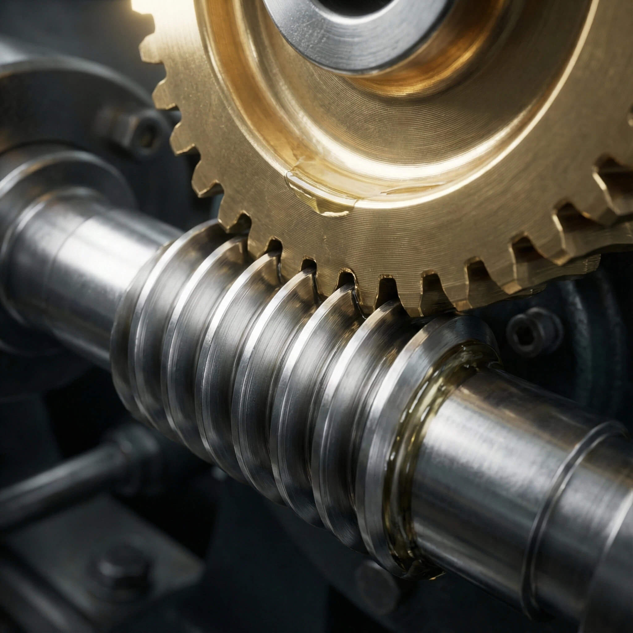
Let’s break it down. You will notice that unlike spur gears, where teeth roll against each other, the contact in a worm gear set is primarily sliding. The system consists of two main components:
- The Worm (Driver): This is a shaft with a spiral thread, resembling a standard screw. It typically acts as the input, driven by a motor.
- The Worm Wheel (Driven): This is the gear that meshes with the worm. Its teeth are curved to match the radius of the worm to maximize contact.
- Axis Orientation: The shafts are almost always perpendicular (90 degrees) to each other and do not intersect.
When the worm rotates, its threads slide across the teeth of the wheel, pushing it forward. This sliding action is what gives the worm gear its smooth, quiet operation, but it is also the source of significant friction, which we will discuss later regarding efficiency.
Understanding the Reduction Ratio
Why does this matter? You can achieve massive speed reduction without a complex, bulky gearbox. In a standard spur gear set, achieving a 50:1 reduction requires multiple stages and gears. A worm gear can achieve this—and even ratios as high as 100:1—in a single stage.
The math is surprisingly simple but powerful:
- Ratio Calculation: The ratio is determined by the number of teeth on the worm wheel divided by the number of “starts” (threads) on the worm.
- Single Start vs. Multi-Start: A single-start worm advances the gear by one tooth for every 360-degree revolution. A multi-start worm advances it by two or three teeth, changing the speed and torque output.
- Space-Saving Benefits: Because you only need two components to drop motor speed from 1500 RPM to 30 RPM, you save significant housing weight and installation space.
KEY TAKEAWAY:
Worm gears provide the highest reduction ratio in the smallest package, making them the most density-efficient torque multipliers in mechanical design.
2. Exploring What the Worm Gear Is Used For in Industry
Worm gears are not a one-size-fits-all solution, but their unique characteristics make them dominant in specific sectors. Knowing where to apply them is key to engineering efficiency.
Precision in Packaging and Automation
Picture this scenario: You are running a high-speed packaging line. Noise and vibration are your enemies, as they fatigue operators and destabilize sensitive sensors. Worm gears are heavily utilized here because the sliding contact reduces the impact noise found in spur gears.
- Conveyor Speed Reduction: They provide the high torque needed to move loaded belts at low speeds.
- Indexing Mechanisms: The friction in the system prevents “over-run” or coasting when the motor stops, ensuring packages stop exactly where they need to.
- Hygiene Requirements: In food processing, enclosed worm gearboxes are easier to seal and clean than complex multi-stage external drivetrains.
Heavy Lifting and Hoisting Equipment
Here is the kicker: You need a system that holds the load even when power fails. In cranes, elevators, and construction hoists, gravity is a constant threat.
- Elevators and Lifts: The gear set acts as a primary transmission and a secondary safety device.
- Construction Hoists: High torque is required to lift heavy materials vertically.
- Garage Door Openers: The compact size fits in ceiling units, while the self-locking nature keeps the door shut.
Tuning and Adjustment Instruments
It’s not just for heavy industry. You interact with worm gears more often than you think in fine-tuning devices where stability is more important than power transmission.
- Musical Instruments: Guitar tuning pegs use worm gears to tighten strings and hold them against the massive tension of the wire.
- Optical Adjustments: Microscopes and telescopes use fine-pitch worm gears for focusing.
- Valve Controls: Industrial flow valves use them to allow an operator to manually close a high-pressure gate with minimal physical effort.
Table 1: Common Applications by Industry
| Industry | Primary Application | Key Gear Requirement | Common Failure Mode |
|---|---|---|---|
| Packaging & Food | Conveyors, Labeling Machines | Quiet operation, Washdown capable | Seal failure leading to contamination |
| Lifting & Construction | Cranes, Hoists, Elevators | High Torque, Self-Locking Safety | Shock loading causing tooth fracture |
| Automotive | Power Steering, Torsen Differentials | Precision feedback, Durability | Overheating due to continuous duty |
| General Automation | Rotary Tables, Indexers | Zero Backlash potential | Pitting due to poor lubrication |
EXPERT ANALYSIS:
Yantong Tech engineers note that 60% of premature failures in these applications stem from selecting generic gears that ignore specific “working conditions.” For example, a worm gear designed for the steady load of a conveyor will fail rapidly if used in a “stop-start” indexing application due to thermal spikes. We recommend assessing the duty cycle before finalizing the gear material.
KEY TAKEAWAY:
From stopping a heavy elevator to tuning a guitar, worm gears are used wherever compact torque and precise holding power are non-negotiable.
3. Why Is the Self-Locking Feature So Critical?
One of the most distinct advantages of the worm gear is its ability to lock in place. This is not magic; it is physics, and understanding it is crucial for safety compliance.
The Physics of Self-Locking
You might be wondering: How does the gear know when to lock? It depends on the relationship between the friction coefficient and the lead angle of the worm. Generally, if the tangent of the lead angle is less than the coefficient of friction, the wheel cannot drive the worm.
- Static Locking: When the motor stops, the friction between the worm and the wheel is too great for the load to overcome.
- Back-Driving: This is the reverse—where the load drives the motor. In spur gears, this happens easily. In worm gears, it is mechanically difficult.
- Vibration Risks: Be aware that external vibration can lower the friction coefficient, momentarily allowing the gear to slip.
Safety Implications for Your Machinery
The bottom line is safety. You gain a built-in safety brake simply by the nature of the gear design, which simplifies your overall machine architecture.
- Load Holding: During power outages, a conveyor on an incline won’t slide backward, dumping product.
- Reduced Complexity: You may be able to downsize or eliminate external caliper brakes, reducing maintenance costs.
- Compliance: Many lifting standards require a mechanical self-locking mechanism; the worm gear fulfills this inherently.
KEY TAKEAWAY:
The self-locking capability allows the gear to act as a secondary brake, providing critical safety redundancy in lifting and holding applications.
4. Which Materials Are Best for Worm Gears?
The sliding action of a worm gear generates heat and wear. If you select the wrong materials, your gearbox will destroy itself in hours.
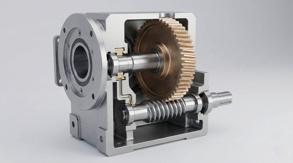
The Importance of Dissimilar Materials
Here is the secret: You must avoid steel-on-steel contact. If both the worm and the wheel are made of hardened steel, the heat from sliding will cause them to seize and gall (welding together microscopically).
- The Worm (Steel): Needs to be hard to resist wear and maintain the thread profile.
- The Wheel (Bronze): Acts as the “sacrificial” wear component. Bronze has a lower friction coefficient against steel and dissipates heat well.
- Anti-Seizing: The microstructure of bronze allows it to conform slightly to the harder steel worm, creating a better contact patch over time.
Manufacturing Matched Sets (The Yantong Approach)
Don’t overlook this detail. You ensure quieter operation and longer life when your manufacturer pairs components during production. At Yantong Tech, we don’t just grab a worm from Bin A and a wheel from Bin B.
- Controlled Contact: We utilize fly-cutting tools that match the exact profile of the mating worm.
- Material Selection: We typically use 20CrMnTi (case hardened) for the worm and Tin Bronze (CuSn12) for the wheel.
- Minimizing Backlash: By lapping the worm and wheel together, we reduce the initial play, ensuring precision from day one.
Table 2: Material Compatibility & Properties
| Component | Common Material | Process | Primary Function |
|---|---|---|---|
| Worm Shaft | 20CrMnTi / 18CrNiMo7-6 | Carburizing & Quenching | Provide high surface hardness (58-62 HRC) to drive the load without deforming. |
| Worm Wheel | CuSn12 (Tin Bronze) | Centrifugal Casting | Provide low friction, heat dissipation, and conformability to the worm shaft. |
| Worm Wheel (Alt) | Aluminum Bronze | Forging / Casting | Used for very heavy loads where shock resistance is higher priority than speed. |
| Hub/Core | Cast Iron / 45# Steel | Casting | Structural support for the bronze ring to reduce material cost. |
EXPERT ANALYSIS:
Choosing the correct bronze alloy is critical; Yantong Tech utilizes specific centrifugal casting methods to ensure the grain structure of the wheel is dense and uniform. Sand-casted bronze often contains porosity that weakens the teeth under load. Our use of centrifugally cast CuSn12 ensures the wheel can withstand the continuous sliding friction demanded by industrial standards.
KEY TAKEAWAY:
Durability relies on material science; a hardened steel worm paired with a high-quality bronze wheel is the industry standard for minimizing friction and wear.
5. What Are the Different Worm Gear Configurations?
Not all worm gears look or act the same. The shape of the gear teeth—specifically the “throat”—determines how much load the system can handle.
Non-Throated Worm Gears
Starting with the basics. You will see this simple helical design in light-load applications. In this configuration, neither the worm nor the gear is curved to wrap around the other.
- Point Contact: The teeth only touch at a single point.
- High Wear: Because the load is concentrated on a tiny dot, these gears wear out quickly if overloaded.
- Manufacturability: These are the easiest and cheapest to produce.
Single-Throated and Double-Throated Designs
Now, let’s upgrade. You get significantly higher torque capacity when the gear wraps around the worm.
- Single-Throated: The worm wheel is concave (curved inward) to wrap around the worm. This changes the contact from a point to a line, drastically reducing pressure and increasing load capacity.
- Double-Throated (Globoidal): Both the worm and the wheel are curved to wrap around each other. This provides “area contact,” allowing for the highest possible torque transmission in the smallest space.
- Precision Requirement: Double-throated gears require incredibly precise axial alignment; even a millimeter of offset can ruin the mesh.
KEY TAKEAWAY:
The “throat” design determines the contact area; double-throated (globoidal) gears offer the highest torque capacity but require the most precise mounting.
6. How Do You Manage Efficiency and Heat Generation?
Every mechanical advantage comes with a trade-off. For the worm gear, that trade-off is energy efficiency.
The Sliding Friction Challenge
Here is the trade-off. You sacrifice some energy efficiency to gain high torque and self-locking capabilities. Because the mechanism relies on sliding, a portion of the input energy is converted into heat rather than rotation.
- Energy Loss: While a spur gear might be 98% efficient, a worm gear typically ranges from 50% to 90%.
- Ratio Impact: Higher reduction ratios (like 100:1) usually have lower efficiency because the lead angle is smaller, resulting in more sliding per revolution.
- Thermal Limits: If the heat isn’t dissipated, the oil thins out, metal touches metal, and the gearbox fails.
Lubrication and Cooling Strategies
Don’t ignore the oil. You cannot use standard gear oil; you need lubricants specifically designed for high sliding friction.
- Synthetic Polyglycols (PAG): These are the gold standard for worm gears. They resist thermal breakdown and have a low coefficient of friction.
- Compounded Oils: These contain fatty acids that help maintain an oil film on the bronze wheel.
- Cooling Design: This is why you often see cooling fins on the casing of worm gearboxes—to radiate the generated heat away from the core.
KEY TAKEAWAY:
While worm gears generate more heat than other types, proper lubrication and housing design allow them to run reliably in continuous-duty cycles.
7. How to Maintain and Troubleshoot Worm Gears?
Even the best-manufactured gears wear out eventually. However, predicting that wear and managing it is what separates reactive maintenance from proactive engineering.
Recognizing Signs of Wear
Watch out for these signs. You might hear a grinding noise or notice increased backlash before catastrophic failure occurs.
- Checking the Contact Pattern: By applying engineering blue to the worm, you can see where it touches the wheel. A shifting pattern indicates bearing wear or misalignment.
- Measuring Backlash: If the free play between the gears increases significantly, the bronze teeth are thinning.
- Visual Inspection: Look for “pitting”—small craters on the bronze surface. This indicates that surface fatigue is setting in.
Replacement and Reverse Engineering
What if the part is obsolete? You don’t need to scrap the machine; you can reverse engineer the gear set. Many older machines use non-standard pitches or modules.
- Mapping Profiles: Yantong Tech can measure a worn gear, determine the original geometry, and calculate the wear compensation.
- Material Analysis: We verify the hardness and chemical composition of the old part to ensure the replacement matches or exceeds the original spec.
- Life Cycle Cost (LCC): Replacing just the gear set is a fraction of the cost of replacing the whole drive unit.
Table 3: Worm Gear Troubleshooting Guide
| Symptom | Probable Cause | Corrective Action |
|---|---|---|
| Overheating | Oil level low or wrong viscosity | Change to synthetic PAG oil; check seals. |
| Excessive Noise | Misalignment or bearing failure | Check mounting alignment; replace bearings. |
| Rapid Tooth Wear | Overloading or lack of lubrication | Verify duty cycle; upgrade wheel material to CuSn12. |
| Back-Driving | Vibration or low friction coefficient | Inspect brake system; ensure worm lead angle is correct. |
EXPERT ANALYSIS:
Regular oil analysis and vibration monitoring can extend the service life of a worm gear set by up to 30%, significantly lowering your Life Cycle Cost (LCC). Yantong Tech supports this by providing full traceability on our materials, so you know exactly what baseline you are measuring against.
KEY TAKEAWAY:
Proactive maintenance and partnering with a supplier capable of reverse engineering ensures that gear wear never turns into prolonged downtime.
Conclusion
We have explored how worm gears offer a unique combination of high reduction ratios, compact design, and self-locking safety that other gear types cannot match. From heavy lifting to precision packaging, they are the silent workhorses of industry. However, their reliance on sliding friction demands a manufacturing partner who understands material science, heat dissipation, and precision tolerances.
Don’t let gear failure compromise your equipment’s reputation. Choose a manufacturing partner who prioritizes Life Cycle Cost (LCC) over short-term savings. With Yantong Tech, you gain a partner specialized in matched-set manufacturing, reverse engineering, and truthful “engineer-to-engineer” support. We don’t just sell parts; we provide the documentation, traceability, and reliability you need to sleep soundly.
Ready to stabilize your supply chain? Contact Yantong Tech for custom worm gear solutions. At Yantong Tech, we drive innovation in gear manufacturing for a more efficient industrial future.
FAQ Section
Q1: Can I drive the worm gear backwards (drive the worm with the wheel)?
Generally, no—this is the “self-locking” feature. Due to the high friction angle and the geometry of the mesh, the wheel usually cannot drive the worm, which provides a safety brake effect. However, under conditions of heavy vibration or low reduction ratios, “back-driving” is physically possible, so safety brakes should still be used in critical lifts.
Q2: What is the best lubrication for worm gears to prevent overheating?
Compounded oils or Synthetic Polyglycols (PAG) are superior. Because the primary action is sliding rather than rolling, you need lubricants with additives that reduce friction and withstand high pressure; standard mineral gear oils often fail to protect the bronze wheel from rapid wear and pitting.
Q3: How do I know if my worm gear is worn out?
Excessive backlash and increased operating noise are the first indicators. You can measure the “play” or free movement in the gear set; if it exceeds manufacturer tolerances, or if you see “pitting” (small holes) on the bronze wheel teeth upon inspection, it is time for a replacement or reverse engineering analysis.
Q4: Why are worm gears less efficient than spur gears?
The inherent sliding action generates significant friction and heat. Unlike spur gears that roll against each other, the worm slides across the wheel teeth, converting some energy into heat, which means efficiency can range from 50% to 90% depending on the ratio and speed, compared to 98% for spur gears.
Q5: What materials does Yantong Tech use for worm gears?
We use a specific pairing of hardened steel and high-grade bronze. To ensure longevity, the worm shaft is typically machined from case-hardened steel (like 20CrMnTi) and ground to precision, while the wheel is made from tin bronze or phosphor bronze (like CuSn12) to provide the necessary lubricity and wear resistance.