
You use the helical gear calculation formula to define tooth geometry on a plane perpendicular to the teeth. Industrial machinery designers often face extreme vibration and premature gear failure due to imprecise mesh specifications. Mastering these mathematical relationships transforms your theoretical blueprints into robust, long-lasting hardware.
How to use helical gear calculation formula in normal systems?
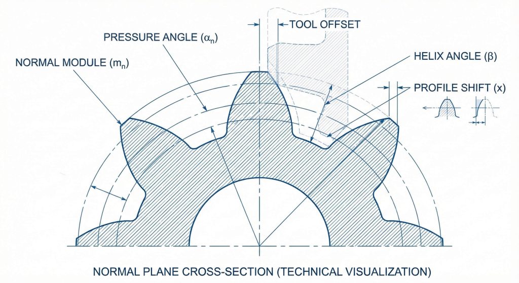
What defines the normal module in this system?
The normal module acts as the primary scaling factor for defining tooth size and spacing within this framework. Here is the deal. You must select standard metric modules to ensure compatibility with a vast range of industrial tools. This precision ensures that your pitch circle definitions remain consistent across different manufacturing batches.
Check this out:
- Selection of standard modules.
- Precise pitch circle definition.
- Tooling compatibility assessments.
- Consistent tooth spacing logic.
How do you manage profile shifts for durability?
Profile shifting represents a strategic modification where you move the cutting tool toward or away from the gear center. You might be wondering how the helical gear calculation formula prevents undercutting in pinions with low tooth counts. You will find that shifting the profile enhances bending strength and improves the overall wear resistance of the contact path.
Here is why:
- Bending strength optimization.
- Undercut prevention logic.
- Contact path resistance.
- Center distance adjustment.
| Parameter | Symbol | System Value |
|---|---|---|
| Normal Module | mn | 2.5 mm |
| Helix Angle | β | 15 Degrees |
| Profile Shift | xn | +0.25 |
| Teeth Number | z | 24 |
Understanding these normal system parameters allows you to bridge the gap between theoretical math and physical reliability.
Key Takeaway: Normal systems facilitate the use of standard tooling while profile shifts offer the flexibility to optimize gear strength.
Does a radial system helical gear calculation formula work?
What characterizes transverse plane geometry?
A radial system helical gear calculation formula defines tooth geometry in the plane of rotation rather than the normal plane. What’s the real story? Working with radial modules makes it easier to calculate exact center distances between parallel shafts in complex housings. You should verify these dimensions to avoid interference during the final assembly of your transmission system.
Here is the deal:
- Radial module conversion steps.
- Transverse pitch analysis.
- Pitch diameter calculation.
- Housing fit verification.
How are radial angle adjustments calculated?
Transverse pressure angles differ from normal pressure angles and require specific trigonometric adjustments for accurate meshing. Ready for the good part? Understanding this variable helps you predict exactly how much radial load the bearings must support during operation. You must account for these forces to prevent premature bearing wear and shaft deflection in heavy machinery.
Check this out:
- Pressure angle transformation.
- Radial load prediction.
- Circular pitch consistency.
- Shaft deflection analysis.
| Radial Metric | Variable | Transverse Value |
|---|---|---|
| Radial Module | mt | 3.106 mm |
| Transverse Angle | αt | 20.647 Degrees |
| Pitch Diameter | d | 74.544 mm |
| Base Diameter | db | 69.756 mm |
Mastering the radial plane ensures that your custom gear designs interface perfectly with specialized high-speed cutting equipment.
Key Takeaway: Radial systems simplify rotation speed analysis and are indispensable for specialized manufacturing methods.
Can a helical gear calculation formula define Sunderland gears?
How do herringbone gear profiles function?
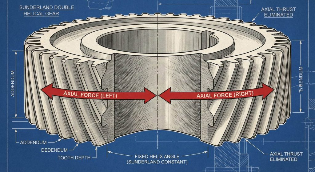
The helical gear calculation formula defines Sunderland gear profiles by utilizing a fixed helix angle of twenty-two point five degrees. Believe it or not the Sunderland method allows for a continuous tooth pattern that offers superior load-carrying capacity. You will notice that this design provides exceptionally smooth power transmission even under fluctuating torque conditions.
Here is why:
- V-shape alignment precision.
- Thrust force cancellation.
- High-torque distribution.
- Vibration dampening.
What are the depth and clearance rules?
Adjusting the whole depth for Sunderland profiles requires following a specific multiplier based on the radial module. Think about this. Failure to reach the correct depth will result in tip interference and mechanical jamming during high-load operation. You must ensure that the root clearance remains sufficient to allow for lubricant flow and thermal expansion.
Check this out:
- Whole depth multipliers.
- Root clearance verification.
- Tooling depth management.
- Thermal expansion space.
| Sunderland Spec | Calculation | Output Result |
|---|---|---|
| Helix Angle | Constant | 22.5 Degrees |
| Whole Depth | 2.188 * mt | 6.80 mm |
| Addendum | 1.000 * mt | 3.11 mm |
| Dedendum | 1.188 * mt | 3.69 mm |
Applying these specific Sunderland constants guarantees that your herringbone gears deliver maximum torque without generating unwanted axial forces.
Key Takeaway: Sunderland double helical gears provide a thrust-free solution for massive torque requirements by utilizing fixed helix angles.
Is the helical gear calculation formula valid for gear racks?
How is linear displacement calculated?
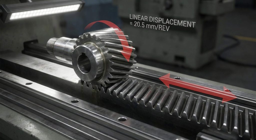
The helical gear calculation formula remains valid for designing a gear rack that converts rotational motion into smooth linear travel. But here’s the kicker. Helical racks provide much smoother motion than straight spur racks because the teeth engage gradually across the face. You can calculate this travel by integrating the radial pitch with the number of teeth on the pinion.
Check this out:
- Linear travel per revolution.
- Radial pitch integration.
- Positioning precision.
- Gradual tooth engagement.
Why match gear hands and orientations?
Matching the hand of the gear and rack is essential because the teeth must lean in the same direction to mesh. It gets better. Proper alignment prevents the pinion from climbing out of the rack under heavy axial loads during rapid acceleration. You should check the mounting distance to ensure that the profile shift coefficients remain within acceptable tolerances for the rack.
Here is why:
- Hand orientation check.
- Mounting distance precision.
- Backlash control logic.
- Axial load stability.
| Rack Element | Metric Symbol | Calculation Basis |
|---|---|---|
| Normal Pitch | pn | π * mn |
| Radial Pitch | pt | pn / cos β |
| Displacement | l | z * pt |
| Helix Angle | β | Matches Pinion |
By following these rack-specific rules you ensure that your linear motion systems operate with high repeatability and minimal noise.
Key Takeaway: Helical racks offer superior linear motion smoothness but require strict adherence to helix angle matching.
How does helical gear calculation formula apply to screw gears?
How to align non-parallel shafts?
You use the helical gear calculation formula for crossed shafts when connecting non-parallel components in a three-dimensional space. What is the catch? The sliding action inherent in this mesh requires careful lubrication management to prevent overheating and rapid surface wear. You will find that screw gears are ideal for secondary drive systems where space constraints limit traditional layouts.
Check this out:
- Shaft angle summation.
- Lubrication stability.
- Housing support design.
- Sliding velocity checks.
What determines screw gear speed ratios?
Determining the velocity ratio involves focusing on the teeth count of the pinion and gear independently of their physical size. Here is the deal. This unique characteristic allows you to design compact gearboxes that fit into tight spaces without sacrificing precision. You must verify that the normal modules are identical for both gears to ensure a valid mesh point.
Here is why:
- Tooth count ratio logic.
- Compact layout design.
- Mechanical advantage.
- Normal module identity.
| Screw Gear | Parameter | Design Context |
|---|---|---|
| Shaft Angle | Σ | 90 Degrees |
| Normal Module | mn | 2.0 mm |
| Teeth Pinion | z1 | 10 |
| Teeth Gear | z2 | 20 |
Screw gears provide the ultimate spatial flexibility for engineers dealing with complex, multi-axis transmission requirements in instrumentation.
Key Takeaway: Crossed helical gears provide unmatched layout flexibility for non-parallel shafts but are limited to light loads.
What helical gear calculation formula finds center distance?
How do you manipulate helix angles?
The helical gear calculation formula finds the exact center distance by balancing pitch diameters with the chosen helix angle. This is the important part. This mathematical relationship allows you to avoid using non-standard modules to fit a specific casing size already in production. You will save significant manufacturing costs by keeping your gear modules within standard ranges.
Here is why:
- Housing diameter control.
- Variable angle adjustment.
- Standard module usage.
- Cost-effective production.
How to optimize housing size?
The sum of the pitch diameters directly equals twice the center distance in a standard parallel gear mesh. You might be wondering how iterative software tools can speed up these complex calculations and verify final geometry for you. You should aim for a compact design that reduces the overall weight and volume of the gearbox assembly.
Check this out:
- Pitch diameter summation.
- Software-aided iteration.
- Weight and volume balance.
- Casing size optimization.
| Spacing Factor | Variable | Mesh Influence |
|---|---|---|
| Center Distance | a | 150.00 mm |
| Helix Angle | β | 20.00 Degrees |
| Pinion Diameter | d1 | 100.00 mm |
| Gear Diameter | d2 | 200.00 mm |
Precision center distance calculations ensure that your gear train operates with minimal backlash and maximum efficiency over time.
Key Takeaway: Center distance is a flexible variable in helical gearing that can be tuned by manipulating helix angles.
How to use helical gear calculation formula for speed ratios?
What are tooth count foundations?
Designers use the helical gear calculation formula to verify speed ratios by focusing on the number of teeth on the mating gears. Ready for a surprise? This principle ensures that your output speed remains constant even if you change the helix angle for housing adjustments. You must ensure that the driving pinion has enough teeth to prevent excessive noise at high rotational speeds.
Check this out:
- Diameter independence logic.
- Discrete tooth count.
- Output speed predictability.
- Noise reduction strategy.
How does sliding velocity impact performance?
Sliding velocity refers to the relative speed at which the teeth rub against each other during the mesh engagement cycle. What’s the real story? High sliding speeds can lead to scuffing and rapid tooth wear if the oil film breaks down under pressure. You need to calculate the sliding component to select the correct viscosity of lubricant for your specific operating temperatures.
Here is why:
- Rolling vs sliding speed.
- Lubricant film thickness.
- Heat generation analysis.
- Viscosity selection logic.
| Ratio Element | Factor | Output Logic |
|---|---|---|
| Input Speed | n1 | 1800 RPM |
| Pinion Teeth | z1 | 15 |
| Gear Teeth | z2 | 60 |
| Output Speed | n2 | 450 RPM |
Relying on tooth counts for speed ratios provides a stable foundation for designing multi-stage reduction units in industrial gearboxes.
Key Takeaway: Velocity ratios in all helical systems are governed by tooth counts ensuring predictable output speeds despite geometric variations.
Does helical gear calculation formula estimate axial thrust?
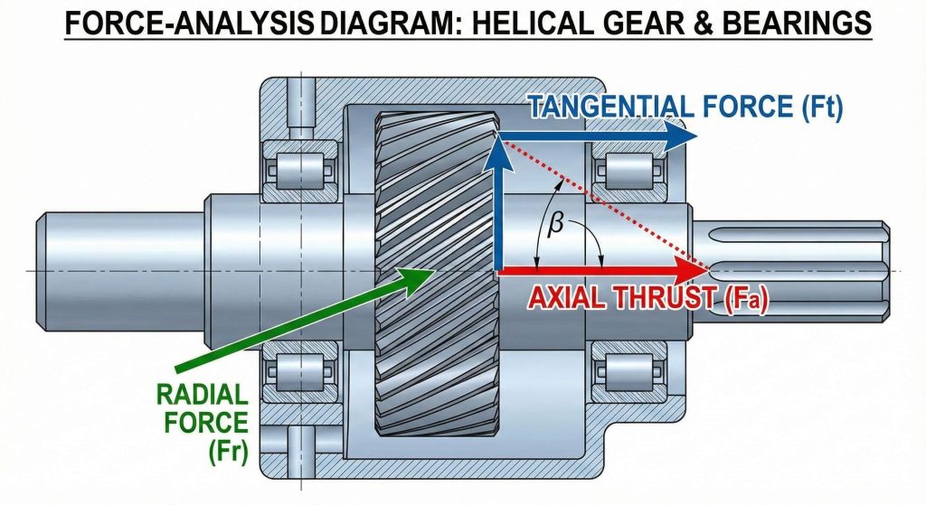
How is load magnitude calculated?
The helical gear calculation formula estimates axial thrust by calculating the forces acting parallel to the gear shaft axis. But here’s the kicker. This thrust load depends directly on the tangent of the helix angle multiplied by the transmitted load on the teeth. You will find that increasing the helix angle dramatically increases the axial force acting on your shaft supports.
Here is why:
- Tangent force derivation.
- Thrust multiplier logic.
- Peak torque safety.
- Angle influence checks.
What is the impact on bearing selection?
Selecting specific bearings like tapered roller types is necessary to handle the combined radial and axial loads of helical gears. Think about this. Using under-sized bearings will lead to rapid failure and potentially catastrophic damage to the entire gear housing assembly. You must verify the thrust direction based on the rotation of the gear and its specific tooth hand orientation.
Check this out:
- Tapered roller selection.
- Axial load capacity.
- Shaft stability check.
- Thrust direction logic.
| Thrust Variable | Symbol | Calculation Result |
|---|---|---|
| Tangent Force | Wt | 5000 N |
| Helix Angle | β | 20 Degrees |
| Axial Thrust | Wx | 1820 N |
| Radial Force | Wr | 1920 N |
Accurate thrust estimation is the only way to guarantee a long service life for your bearings and gearbox components.
Key Takeaway: Precise axial thrust estimation is vital for selecting bearings that can withstand unique directional forces.
Can a helical gear calculation formula help bevel gear design?
What is pitch cone geometry?
Adapting the helical gear calculation formula for bevel gears requires a shift from cylindrical to conical geometry calculations in your workflow. Ready for the good part? Mastering this geometry allows you to design efficient right-angle drives for differential units and industrial mixers. You must ensure the shaft intersection point remains perfectly aligned to prevent tooth tip interference and excessive noise.
Check this out:
- Conical pitch logic.
- Intersection alignment.
- Surface mapping rules.
- Right-angle drive design.
What are heel and toe dimensions?
Measuring the tooth heel involves taking dimensions at the largest part of the gear tooth located at the outer edge. Here is the deal. Tooth dimensions plus pitch diameters always refer to the outer end of the gear heel in metric systems. You should recognize that the face width is limited by the point where the teeth vanish at the cone apex.
Here is why:
- Outer heel reference.
- Inner toe limits.
- Tapering dimension check.
- Face width boundaries.
| Bevel Element | Symbol | Reference Value |
|---|---|---|
| Pitch Angle | δ | 45 Degrees |
| Outer Module | m | 4.0 mm |
| Face Width | b | 30.0 mm |
| Mounting Dist | M | 120.00 mm |
Utilizing conical pitch logic ensures that your right-angle power transmissions are as efficient as your parallel helical gear sets.
Key Takeaway: Bevel gear design relies on conical geometry and outer heel measurements to ensure precise power transmission.
Why use helical gear calculation formula for Gleason types?
What are spiral bevel enhancements?
Applying Gleason standards within your helical gear calculation formula workflow ensures maximum durability for spiral bevel systems. What is the catch? These gears require matching hands where a left-hand pinion must always mesh with a right-hand gear for compatibility. You will find that the spiral angle allows for multiple teeth to be in contact at all times during rotation.
Check this out:
- Overlapping contact ratio.
- Gradual engagement.
- Hand orientation rules.
- High torque capacity.
How does crowning increase tooth strength?
Tooth crowning involves making the gear teeth slightly convex along their length to localize the contact point in the center. It gets better. This feature ensures that the load remains centered on the strongest part of the tooth profile during shaft deflection. You will find that crowned gears are much more tolerant of small misalignments in the gearbox housing during heavy operation.
Here is why:
- Convexity contact logic.
- Alignment tolerance.
- Load centering technique.
- Deflection management.
| Gleason System | Feature | Performance Benefit |
|---|---|---|
| Spiral Bevel | Curved Teeth | Quiet Operation |
| Coniflex | Crowning | Misalignment Tolerance |
| Zerol | Zero Spiral | Low Axial Thrust |
| Profile Shift | Pinion+/Gear- | Balanced Strength |
Implementing Gleason standards transforms standard bevel drives into high-performance components capable of enduring extreme mechanical stress.
Key Takeaway: Gleason spiral bevel systems use advanced crowning and profile shifts to provide maximum durability.
FAQ
Q1: Can I calculate helical gears for non-90 degree shafts?
Yes, you should ensure the sum or difference of the helix angles matches your specific mechanical layout requirements exactly.
Q2: What’s the best way to handle high axial thrust in a small gearbox?
Using a double helical or herringbone design represents the most effective solution because it naturally cancels out axial forces internally.
Q3: How do I know if my helical gear calculation formula requires a profile shift?
You must apply a profile shift if your pinion has a low tooth count or if your center distance is non-standard.
Q4: Can I replace straight bevel gears with Zerol bevels without changing the mounting?
Yes, Zerol bevels are functionally similar to straight bevels and typically require no mounting changes for high-precision needs.
Q5: How do I know if the axial thrust will exceed my bearing capacity?
You must calculate the thrust load using the helix angle and transmitted torque; if the result exceeds the bearing’s rated axial load, you need a different bearing.
Conclusion
Precision in gear technology defines the boundary between mechanical excellence and system failure. By mastering these calculation formulas and understanding the nuances of helical and bevel meshes, you ensure your designs meet the highest industrial standards for performance and longevity. We are dedicated to providing the technical expertise and high-quality components required for your most challenging engineering projects. For personalized technical support or to source precision-engineered gear components, please contact us today. Our vision is to empower global innovation through unmatched mechanical precision and engineering excellence.