A gear module is the ratio of the pitch diameter to the number of teeth in metric systems. Designing high-performance transmission systems becomes a massive technical hurdle when mating components suffer from incorrect sizing. Mismatched dimensions lead to excessive vibration, localized heating, and catastrophic hardware failure during peak operation. You can effectively eliminate these engineering risks by consulting a helical gear module table to ensure absolute manufacturing precision.
What is a helical gear module table for racks?
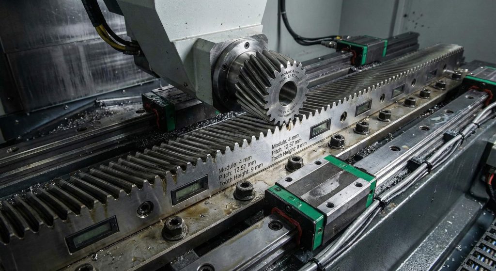
A helical gear module table for racks provides the standardized metric values needed to match linear gear bars with their corresponding pinions. This reference ensures that the tooth thickness and pitch of the rack align perfectly with the circular gear to convert rotary motion into linear displacement. By following these established sizes, you can maintain DIN 6–9 accuracy across long-travel axes in CNC machines.
What are standard rack modules?
Standard rack modules typically range from m1 to m12 to accommodate various load capacities and precision requirements. These values dictate the physical height and width of the teeth machined along the steel bar.
The best part?
- Standardizing modules allows for the seamless jointing of multiple rack segments.
- It ensures that replacement pinions are always compatible with existing installations.
- Uniform sizing reduces the need for custom cutting tools during manufacturing.
Key Takeaway
| Component | Metric Role | Benefit |
|---|---|---|
| Gear Rack | Linear Path | Repeatable Positioning |
| Pinion | Rotary Drive | Smooth Engagement |
Selecting the correct rack module ensures that high-speed gantry systems operate without velocity ripple or premature wear.
Why use a helical gear module table for design?
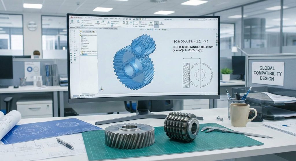
A helical gear module table is used during the design phase to select preferred tooth sizes that simplify procurement and manufacturing. Utilizing standardized metric units ensures that your drivetrain components are compatible with universal hobs and grinding tools. This prevents the high costs and long lead times associated with custom geometric profiles.
Why prioritize standard values?
Prioritizing standard values from the ISO preferred series ensures that replacement parts are readily available worldwide. It allows maintenance teams to source components from different suppliers without risking geometric interference.
Think about it:
- Standard modules like 2.0 or 3.0 are stocked by most industrial distributors.
- Using common sizes facilitates easier reverse engineering of worn equipment.
- It streamlines the CAD modeling process for complex multi-stage gearboxes.
Key Takeaway
| Standard Type | Common Modules | Inventory Status |
|---|---|---|
| Row I | 1.0, 1.5, 2.0 | High Availability |
| Row II | 1.75, 2.25, 2.75 | Special Order |
Adhering to a standardized module system is a strategic decision that lowers the total cost of ownership for industrial machinery.
How does a helical gear module table define bevels?
A helical gear module table defines bevel gears by establishing the tooth size at the large end of the conical pitch surface. This standardized metric value is critical for ensuring that intersecting shafts at 90 degrees mesh with a verified contact pattern. It allows for the precise calculation of cone angles and mounting distances required for heavy-duty angular drives.
How are angular teeth measured?
Angular teeth are measured based on the transverse module at the outer diameter to define the basic gear geometry. This value remains the primary reference for selecting the correct gear planer or CNC milling cutter.
The best part?
- Verified modules ensure uniform load distribution across the face width.
- Standardized bevel modules support ratios ranging from 1:1 to 1:10.
- It simplifies the alignment process during final assembly in differentials.
Key Takeaway
| Gear Type | Reference Point | Critical Metric |
|---|---|---|
| Straight Bevel | Large End | Pitch Diameter |
| Spiral Bevel | Normal Plane | Cutter Radius |
Using a master module table ensures that angular transmission systems provide maximum torque capacity with minimal operating noise.
Can a helical gear module table improve precision?
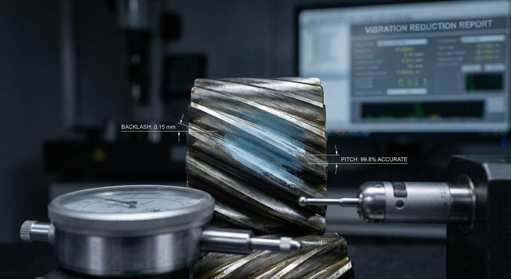
A helical gear module table improves precision by providing the exact mathematical relationships needed to control backlash and tooth engagement. By adhering to these standardized values, you can maintain tighter tolerances during the finish grinding and lapping processes. This results in smoother power transmission and a significant reduction in mechanical vibration during high-speed operation.
Does center distance matter?
Center distance is directly calculated from the transverse module and tooth count to ensure the gears operate on their theoretical pitch lines. Even small deviations in the module can lead to improper contact and localized tooth overheating.
Think about it:
- Precise module matching eliminates the “knocking” sound found in poor gearsets.
- It allows for the calculation of tip relief to improve NVH performance.
- Tighter tolerances extend the service life of internal bearings and seals.
Key Takeaway
| Precision Metric | Impact | Success Metric |
|---|---|---|
| Backlash | Tooth Play | < 0.05 mm |
| Pitch Error | Motion Smoothness | ISO Grade 6 |
High-precision gearboxes depend on exact module synchronization to achieve the reliability required for robotics and automated production.
Which helical gear module table helps spur gear selection?
A helical gear module table for spur gears assists in selecting the optimal tooth size for parallel-shaft power transmission. This reference provides the necessary data to balance tooth strength against the physical size constraints of the machine housing. It is the foundational tool for designing conveyors, reducers, and general industrial automation systems.
Which spur modules are common?
Common spur gear modules range from m0.5 for small electronics to m12 for heavy industrial mill drives. Selecting a module from Row I ensures that you can find standard hobs for high-volume CNC production.
The best part?
- Spur gears with the same module can be easily swapped to change ratios.
- Standardized bores and keyways often follow specific module size clusters.
- It simplifies the calculation of the outside diameter for housing clearance.
Key Takeaway
| Industry | Typical Module | Material Choice |
|---|---|---|
| Automation | m1.0 – m2.5 | 40Cr / C45 |
| Heavy Mining | m8.0 – m12.0 | 20CrMnTi |
Consistent spur gear module selection ensures that parallel drive systems are both maintainable and efficient over long service intervals.
Does a helical gear module table verify compatibility?
A helical gear module table verifies compatibility by acting as a universal benchmark for mating gear geometries across different manufacturers. If two gears do not share the same module value, their teeth will physically interfere and fail to rotate. This verification step is mandatory during repair work where an OEM part must be replaced by a custom-manufactured component.
How to check tooth engagement?
Tooth engagement is checked by measuring the pitch or calculating the module from the outside diameter and tooth count. A perfect match ensures that the gears roll together rather than sliding, which minimizes friction and heat.
Think about it:
- Mismatched modules can cause a total system lockup within seconds of startup.
- Verifying the module prevents the accidental mixing of metric and imperial parts.
- It ensures that the pressure angles of both gears are geometrically aligned.
Key Takeaway
| Match Status | Result | Operational Impact |
|---|---|---|
| Identical | Rolling Contact | High Efficiency |
| Different | Sliding Interference | Mechanical Failure |
Absolute module compatibility is the primary safeguard against catastrophic drivetrain failure in high-torque industrial environments.
What defines a helical gear module table for worm sets?
A helical gear module table for worm sets defines the axial module of the worm shaft and the corresponding transverse module of the wheel. This dual-plane definition is essential for achieving high reduction ratios and self-locking capabilities in compact right-angle drives. It ensures that the bronze worm wheel and hardened steel worm mesh with a verified contact pattern.
Why use bronze worm wheels?
Bronze worm wheels are used because their material properties offer low friction and high wear resistance when paired with a hardened steel worm. This pairing ensures that wear occurs preferentially on the replaceable wheel component rather than the expensive worm shaft.
The best part?
- Standard modules support reduction ratios ranging from 5:1 to 100:1.
- Correct module matching ensures smooth, quiet operation in packaging lines.
- It allows for the precise calculation of lead angles for efficiency optimization.
Key Takeaway
| Component | Material | Hardness |
|---|---|---|
| Worm Shaft | 40Cr Steel | HRC 50–60 |
| Worm Wheel | Tin Bronze | As-Cast/Machined |
Precision-matched worm gear modules are vital for systems where holding torque and safety are critical requirements.
How to read a helical gear module table accurately?
Reading a helical gear module table accurately requires identifying the specific measurement plane, such as the normal or transverse plane. You must distinguish between the normal module used for tooling and the transverse module used for center distance. This distinction is vital for helical gears where the teeth are cut at a specific helix angle.
What is the normal module?
The normal module is measured perpendicular to the tooth trace and is the standard value used to select the cutting hob. Most manufacturers prioritize this value to maintain consistency with global ISO preferred series.
Think about it:
- The normal module remains constant even if you change the helix angle.
- It determines the base structural strength of the gear tooth at the root.
- All standard gear-cutting hobs are labeled by their normal module size.
Key Takeaway
| Measurement Plane | Formula | Design Role |
|---|---|---|
| Normal | Transverse * cos(angle) | Tooling Selection |
| Transverse | Pitch Dia / Teeth | Layout Planning |
Correctly identifying the module plane prevents the common error of miscalculating shaft center distances in complex transmission housings.
Why is a helical gear module table vital for spiral gears?
A helical gear module table is vital for spiral gears because it ensures the curved teeth provide gradual engagement and quiet operation. This standardized sizing allows for the optimization of the contact ratio, which is essential for high-speed automotive and aerospace applications. It provides the geometric foundation for Gleason or Klingelnberg cutting methods.
Why is NVH performance important?
NVH performance is critical for passenger comfort and the long-term structural integrity of your vehicle’s drivetrain. Spiral gears with matched modules significantly reduce high-pitched whining and mechanical resonance.
The best part?
- Spiral modules support compact drive designs with very high power density.
- They distribute loads across more surface area to prevent surface pitting.
- Standardized sizing allows for the use of matched sets for easier replacement.
Key Takeaway
| Performance Metric | Spiral Benefit | Industrial Result |
|---|---|---|
| Noise | Gradual Entry | Quiet Operation |
| Strength | Curved Geometry | High Shock Load |
Implementing spiral gears with verified modules is the most effective way to improve the refinement of modern right-angle drive systems.
What is the most common helical gear module table error?
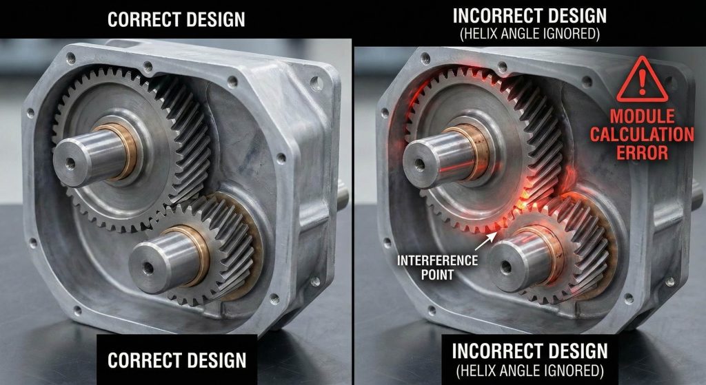
The most common error in a helical gear module table is failing to account for the helix angle when calculating the pitch diameter. This mistake leads to the manufacturing of gears that will not fit into their intended machine housings. Using the table correctly involves verifying every dimension against the theoretical line of contact to ensure total system harmony.
How can I avoid calculation mistakes?
Avoiding calculation mistakes requires double-checking the relationship between the normal and transverse modules using the cosine of the helix angle. You should always verify your final dimensions against the standardized values in a master reference chart.
Think about it:
- Using a digital calculator ensures that trigonometric functions are accurate.
- Professional CAD software can automate the conversion between module planes.
- Peer-reviewing gear drawings prevents simple decimal errors in large-scale projects.
Key Takeaway
| Error Type | Solution | Prevention |
|---|---|---|
| Plane Mix-up | Define Reference | Use ISO Standards |
| Helix Neglect | Apply Cosine Law | Software Verification |
Correctly applying the helix angle ensures that your power transmission components are perfectly aligned for peak efficiency.
Helical Gear Module FAQ
Can I mesh different modules together?
No. Gears will only mesh correctly if they share identical module values to ensure the tooth geometries are perfectly aligned.
What’s the best module for high-speed use?
Smaller modules are typically better for high-speed applications because they offer more teeth for a given diameter, improving engagement smoothness.
How do I know if I have a metric module?
Measure the pitch diameter and divide it by the number of teeth; if the result is a whole or standard fractional number in millimeters, it is a metric module.
Can I convert DP to module?
Yes. You can convert imperial Diametral Pitch to metric by dividing 25.4 by the current pitch value to find the equivalent module.
How do I know if a table is ISO compliant?
Check if the table prioritizes Row I values such as 1.0, 1.5, and 2.0, as these are the primary universal standards.
Conclusion
Standardizing your transmission components through a master module system is the most effective way to ensure long-term mechanical stability. By matching profiles exactly and adhering to global ISO standards, you protect your equipment from the expensive risks of vibration and premature tooth failure. Our engineering-backed approach ensures stable delivery schedules and consistent quality across every batch. To secure high-performance gears for your next project, contact us today to receive an expert consultation and a detailed technical quote.