Incorrect selection of the pressure angle of helical gear components leads to premature tooth breakage or excessive vibration in your machinery. If you get this wrong by even a single degree, you can reduce load capacity by 20%, causing catastrophic downtime. This guide provides the exact formulas and selection criteria used by top-tier manufacturers to ensure your helical gear designs remain stable and robust.
1. What is the pressure angle of helical gear?
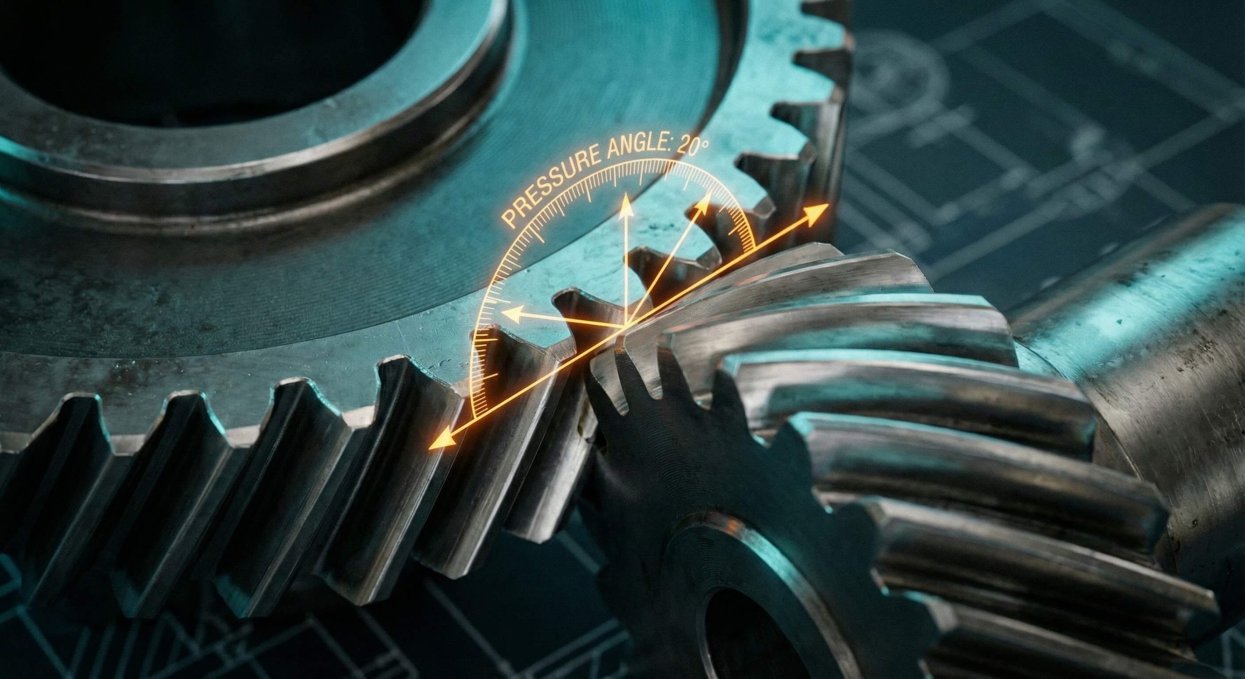
The pressure angle of helical gear is the angle at the pitch point between the line of pressure (normal to the tooth surface) and the plane tangent to the pitch surface. This angle defines the direction in which the force is transmitted between the mating teeth of two gears.
Here’s the deal.
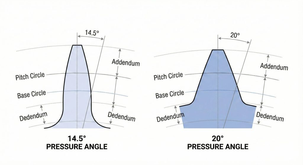
The pressure angle essentially dictates the shape of the involute curve. A standard 20° angle creates a tooth that is wider at the base, providing better resistance to bending. Conversely, a 14.5° angle results in a thinner tooth profile that allows for a higher contact ratio, which is beneficial for specific low-load applications where silence is the primary requirement.
Key Takeaway: The pressure angle determines the fundamental geometry of force transmission and tooth strength.
| Standard Angle | Primary Application | Characteristics |
|---|---|---|
| 14.5° | Legacy systems, noise-sensitive units | Quiet operation, lower tooth strength |
| 20° | Modern industrial gearboxes | Balanced strength and efficiency |
| 25° | Heavy-duty, high-shock equipment | Maximum beam strength, higher noise |
2. Why does the pressure angle of helical gear matter for shafts?
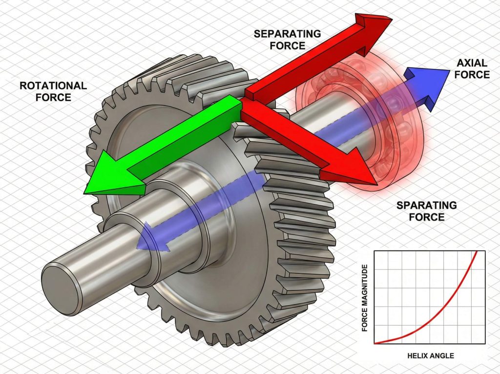
The pressure angle of helical gear is a primary factor in determining the magnitude of separating forces that your bearings and gear shaft must withstand during operation. When teeth engage, the pressure angle splits the transmitted force into two components: a tangential force that does the work and a radial force that tries to push the gears apart.
You might be wondering.
As you increase the pressure angle, the radial (separating) force grows. This increases the load on your shafts and bearings, potentially requiring heavier-duty components to prevent deflection. If your shaft lacks the rigidity to handle these forces, the gears will lose their ideal alignment, leading to rapid wear and tooth pitting.
Key Takeaway: Higher pressure angles increase tooth strength but significantly raise the load on supporting shafts.
| Angle Type | Separating Force | Tooth Strength | Bearing Load |
|---|---|---|---|
| Low (14.5°) | Minimal | Lower | Standard |
| Medium (20°) | Moderate | High | Moderate |
| High (25°) | High | Maximum | High |
3. How does the normal vs transverse pressure angle of helical gear differ?
You must distinguish between the normal and transverse pressure angle of helical gear because they represent the geometry in two distinct planes of measurement. The normal pressure angle ($\alpha_n$) is measured in a plane perpendicular to the tooth helix, while the transverse pressure angle ($\alpha_t$) is measured in the plane of rotation.
What’s the real story?
Because helical teeth are wrapped around a cylinder at an angle, the effective pressure angle you see from the side of the gear (transverse) is always larger than the angle measured perpendicular to the tooth (normal). Most gear cutters are standard to the normal plane, but your center distance and assembly calculations depend entirely on the transverse plane values.
Key Takeaway: Helical gears require dual-plane analysis to account for the helix angle’s geometric influence.
| Plane | Designation | Definition | Context |
|---|---|---|---|
| Normal Plane | $\alpha_n$ | Perpendicular to the tooth face | Tooling and cutting standards |
| Transverse Plane | $\alpha_t$ | Perpendicular to the gear axis | Mesh and center distance math |
4. How do you calculate the transverse pressure angle of helical gear?
To calculate the transverse pressure angle of helical gear, you must apply the geometric relationship where the tangent of the transverse angle equals the tangent of the normal angle divided by the cosine of the helix angle. This formula is vital when you are transitioning from standard bevel gear logic to complex helical meshes.
Ready for the good part?
The mathematical formula is expressed as:tan(αt) = tan(αn) / cos(β)
Where $\alpha_t$ is the transverse angle, $\alpha_n$ is the normal angle, and $\beta$ is the helix angle. Using this calculation ensures that the gears you manufacture will mesh at the correct center distance without interference. Accurate calculations are especially vital for pinions with low tooth counts to prevent undercutting.
Key Takeaway: Correct transverse calculations are required to maintain proper tooth engagement and center distance.
| Parameter | Symbol | Role in Calculation |
|---|---|---|
| Normal Angle | $\alpha_n$ | The base input (usually 20°) |
| Helix Angle | $\beta$ | The “wrap” angle of the teeth |
| Transverse Angle | $\alpha_t$ | The resulting working pressure angle |
5. What is the best pressure angle of helical gear for high load?
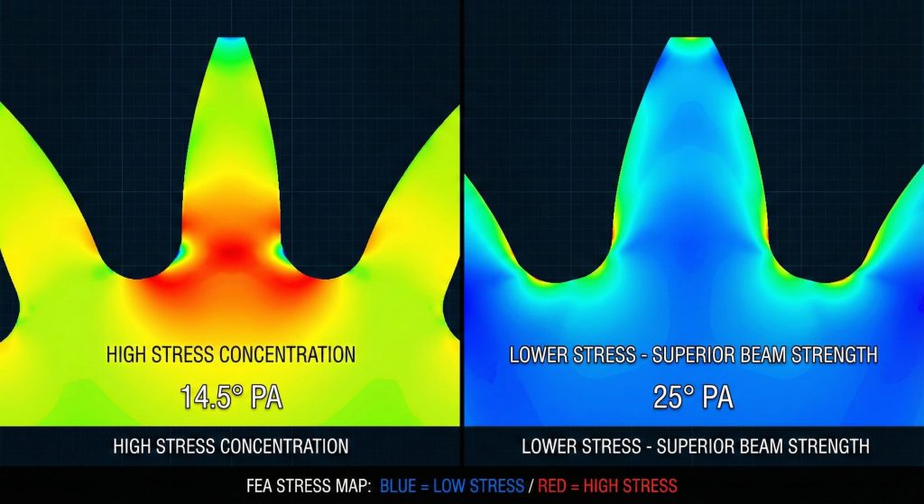
The best pressure angle of helical gear for high-torque applications is generally 20° or 25°, as these angles produce a tooth with a thicker root and higher beam strength. These profiles are less susceptible to bending fatigue, which is the most common failure mode in heavy-duty machinery.
But wait, there’s more.
While 25° offers the highest theoretical load capacity, it can be noisier and generates higher separating forces. For most industrial equipment, 20° is recognized as the “sweet spot.” It provides 15-20% more strength than a 14.5° tooth without the excessive bearing wear associated with 25° or 30° profiles.
Key Takeaway: A 20° pressure angle offers the best balance of load capacity, efficiency, and durability for modern equipment.
| Pressure Angle | Bending Strength | Shock Resistance | Wear Life |
|---|---|---|---|
| 14.5° | Low | Low | Moderate |
| 20° | High | High | High |
| 25° | Maximum | Maximum | Moderate |
6. Can the pressure angle of helical gear reduce operational noise?
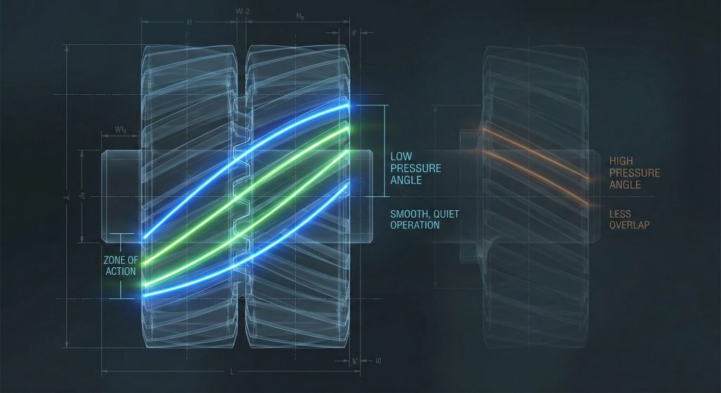
Reducing the pressure angle of helical gear to 14.5° can lower operational noise because it increases the contact ratio, meaning more teeth are in contact at any given time. This gradual engagement is similar to the smooth transition found in a worm gear set.
This is where it gets interesting.
Noise in gearboxes often stems from the impact of teeth entering the mesh. A lower pressure angle makes the teeth “longer,” allowing the load to transfer more gently. However, you must be careful; if the load is too high, these thinner teeth may deflect or break. In high-precision automation, engineers often stick to 20° but apply profile modifications to achieve the same silencing effect without losing strength.
Key Takeaway: Lower pressure angles provide quieter operation by increasing the average number of teeth in simultaneous contact.
| Feature | Low Pressure Angle (14.5°) | Standard Pressure Angle (20°) |
|---|---|---|
| Contact Ratio | Higher | Moderate |
| Engagement | Very Gradual | Standard |
| Vibration Level | Low | Moderate |
7. How does the helix angle affect the pressure angle of helical gear?
The helix angle directly influences the transverse pressure angle of helical gear, causing it to increase as the teeth become more “twisted” around the gear body. This geometric interplay is what gives helical gears their characteristic smoothness compared to straight-cut spur gears.
Bottom line?
As your helix angle ($\beta$) grows, the transverse pressure angle ($\alpha_t$) grows with it. This means a gear with a 45° helix angle will experience a much higher separating force than a gear with a 15° helix angle, even if they both started with a 20° normal pressure angle. You must account for this when designing housings to ensure they don’t flex under the increased axial and radial loads.
Key Takeaway: Increasing the helix angle forces the transverse pressure angle higher, requiring sturdier bearing supports.
| Helix Angle ($\beta$) | Normal Angle ($\alpha_n$) | Resulting Transverse Angle ($\alpha_t$) |
|---|---|---|
| 0° (Spur) | 20° | 20.00° |
| 15° | 20° | 20.65° |
| 30° | 20° | 22.80° |
| 45° | 20° | 27.24° |
8. Does the pressure angle of helical gear impact transmission efficiency?
The pressure angle of helical gear impacts transmission efficiency by altering the sliding velocity between teeth; generally, higher pressure angles reduce sliding friction and improve efficiency.
Think about it.
Higher pressure angles result in more “rolling” and less “sliding” as the teeth pass through the pitch point. Since sliding is the primary source of heat and friction loss in gear systems, a 20° or 25° angle often runs cooler and more efficiently than a 14.5° angle. If you are designing for high-speed power transmission, choosing a standard 20° angle helps you maintain efficiencies in the 98% to 99% range.
Key Takeaway: Higher pressure angles improve efficiency by reducing energy losses associated with sliding friction.
| Pressure Angle | Sliding Friction | Rolling Action | Typical Efficiency |
|---|---|---|---|
| 14.5° | Higher | Lower | 96% – 97% |
| 20° | Moderate | Higher | 98% – 99% |
| 25° | Lower | Maximum | 98.5% – 99% |
9. What is a profile shifted pressure angle of helical gear application?
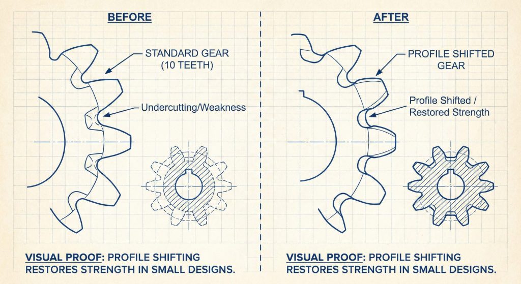
A profile shifted pressure angle of helical gear application is a design technique where you move the cutter’s reference line to alter the tooth thickness and working pressure angle. This is used to prevent undercutting on small pinions or to adjust center distances in a fixed housing.
The best part?
By applying a positive profile shift, you can use a pinion with as few as 10 or 12 teeth without weakening the root. This shift increases the effective pressure angle during operation, resulting in a tooth that is significantly stronger and more resistant to fatigue. It is a favorite technique for engineers trying to pack high power into compact spaces.
Key Takeaway: Profile shifting allows you to optimize tooth strength and prevent manufacturing defects in small-diameter gears.
| Dimension | Standard Helical Gear | Profile-Shifted Helical Gear |
|---|---|---|
| Root Thickness | Standard | Increased (Stronger) |
| Undercut Risk | High (on small gears) | Low |
| Center Distance | Fixed by Module | Adjustable |
10. How do you select the right pressure angle of helical gear for your design?
You select the right pressure angle of helical gear by evaluating your application’s primary constraints: if you need high load capacity, choose 20° or 25°; if you require extreme silence at low loads, 14.5° is the better option.
Now you’re ready.
Most modern industrial applications utilize the 20° pressure angle as the standard because it offers the best reliability for the cost. However, you should always consult with your manufacturing partner to ensure the chosen angle doesn’t create excessive bearing loads that your current housing cannot support. Balancing strength, noise, and heat generation is the hallmark of a successful gear design.
Key Takeaway: Base your pressure angle selection on the dominant failure mode of your specific operating environment.
| Design Goal | Recommended Angle | Reason |
|---|---|---|
| Strength First | 20° – 25° | Resists bending and shock |
| Quiet First | 14.5° – 20° | Smooth engagement, higher overlap |
| Space Saving | 20° + Shift | Prevents root weakening |
Conclusion
Mastering the pressure angle is the foundation of high-performance transmission design. By balancing load capacity with operational noise and efficiency, you ensure your equipment runs longer with fewer breakdowns. Whether you are building heavy-duty excavators or precision planetary gear systems, the right angle makes all the difference.
Frequently Asked Questions
Q1: What is the most common pressure angle for helical gears?
20° is the modern industry standard, offering an optimal balance of strength, efficiency, and manufacturability.
Q2: How does the pressure angle affect the gear’s contact ratio?
Higher pressure angles decrease the contact ratio. While this makes teeth stronger, it can lead to slightly noisier operation compared to lower angles.
Q3: Why use a 14.5° pressure angle today?
It is primarily used for legacy replacements or in specific applications where noise reduction is the absolute priority over load capacity.
Q4: What happens if mating gears have different pressure angles?
They will not mesh correctly. This leads to immediate tooth interference, massive vibration, and catastrophic failure of the gear set.
Q5: Does the pressure angle affect the base circle diameter?
Yes. The base circle is derived directly from the pitch circle and the pressure angle ($D_b = D_p \times \cos(\alpha)$). Changing the angle changes the entire tooth involute.