Introduction
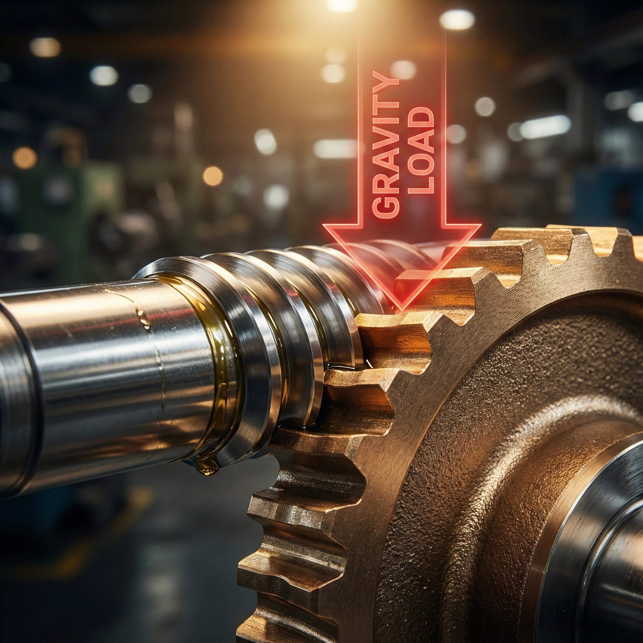
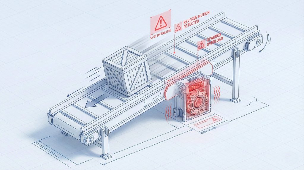
Many engineers and procurement managers operate under a dangerous assumption: that all worm gear systems are inherently self-locking and will never back drive under load. This belief is a silent hazard in industrial design. You might design a vertical lift or an inclined conveyor, convinced that the gearbox will hold the load when power cuts out, only to find gravity has other plans. Relying on this misconception leads to catastrophic failures—vertical lifts plummeting, conveyor belts rolling backward, and costly safety violations. If you assume a gear is self-locking when the physics say otherwise, you are gambling with equipment lifespan and operator safety.
The ability to back drive a worm gear isn’t magic; it is a calculable result of lead angles, friction coefficients, and manufacturing precision. By understanding the mechanics of worm gear back drive, you can select the right components, ensure genuine safety, and optimize your transmission design. Achieving predictable transmission behavior requires strict control over ISO-grade tolerances, a standard that manufacturers like Yantong Tech prioritize to ensure that “self-locking” is a calculated feature, not a lucky accident.
Understanding the Mechanics of Worm Gear Back Drive
What Exactly is Back Driving?
You might be wondering… why a gearbox designed to reduce speed would ever reverse direction. Back driving occurs when the output shaft (the worm wheel) applies enough torque to drive the input shaft (the worm) in reverse. Standard operation reduces speed, but heavy output loads can overcome internal mesh friction, distinguishing static self-locking from dangerous dynamic back driving.
- Input force typically drives the load, but gravity can turn the load into the input force.
- Static friction resists initial movement, while dynamic friction is weaker once moving.
- The “Lead Angle” serves as the primary geometric gatekeeper for this phenomenon.
How Lead Angle Dictates Reversibility
Here is the deal: the geometry of the worm thread effectively decides the rules of engagement. If the friction angle of the materials is greater than the lead angle of the worm, the system will theoretically self-lock. Engineers generally accept that lead angles below 5 degrees result in self-locking, while those above 15 degrees allow axial force to spin the worm easily.
- Low lead angle (High Ratio) creates High Friction and self-locking tendencies.
- High lead angle (Low Ratio) creates High Efficiency and back-driving capabilities.
- Mathematical thresholds exist, but real-world variables often blur these lines.
Can You Rely on Friction for Holding?
But there is a catch. Friction is never a constant variable in industrial environments, fluctuating with temperature, wear, and lubrication status. A brand-new gearbox might hold a load perfectly during acceptance tests, yet fail months later after the gears have “run in” and surface roughness drops. Theoretical calculations often use static coefficients, but micro-movements can instantly switch the system to a lower dynamic friction state.
- Surface polishing during the “running-in” period lowers holding power.
- Temperature spikes cause material expansion and lubricant viscosity changes.
- Theoretical calculations fail because they cannot predict environmental chaos.
| Lead Angle (degrees) | Self-Locking Probability | Efficiency Trend | Typical Application |
|---|---|---|---|
| < 3° | Very High (Static) | Low (40-50%) | Hoists, Screw Jacks |
| 3° – 6° | Uncertain (Gray Zone) | Medium | General Conveyors |
| > 10° | Low (Back-Drivable) | High (70-85%) | High-Speed Drives |
| > 20° | None (Fully Reversible) | Very High | Centrifuges, Coasting Loads |
Key Takeaway: Friction is a dynamic variable, not a constant. While lead angle is the primary indicator of worm gear back drive potential, environmental factors like temperature and break-in periods can drastically reduce holding power over time.
Factors That Enable or Prevent Back Driving
Does Lubrication Affect Self-Locking?
Consider this fact: the oil you choose acts as a wedge between metal surfaces, directly manipulating the friction coefficient. While high-performance synthetic oils (like PAG) extend life and reduce heat, their slippery nature significantly lowers friction compared to mineral oils. This boundary lubrication layer prevents the metal-to-metal contact required for self-locking, potentially turning a holding gear into a reversing one.
- Mineral oil generally supports higher static friction than Synthetic PAG oil.
- Heat reduces viscosity, thinning the oil film and altering friction dynamics.
- Boundary lubrication layers can effectively disable the “locking” mechanism.
How Vibration Breaks Static Friction
It gets even riskier. External vibration acts as a catalyst that transforms static friction into dynamic friction through the “stick-slip” phenomenon. If nearby machinery introduces dithering, the microscopic contact points separate momentarily, allowing gravity to pull the load down incrementally. In these dynamic environments, your calculated static friction vanishes, leaving only the much lower dynamic friction to hold the load.
- Nearby machinery can transmit vibration through the frame to the gearbox.
- Shock loads momentarily reduce contact pressure, breaking the friction grip.
- Stick-slip phenomenon creates a “creeping” descent that accelerates.
Manufacturing Quality and Surface Finish
Here is the bottom line: the microscopic texture of the gear teeth dictates how they grip one another. Yantong Tech utilizes precision grinding to achieve consistent surface finishes, avoiding the dangerous drop in friction that occurs when rough gears eventually wear smooth. This ensures the friction coefficient remains stable over the gear’s life rather than starting high and dropping dangerously low.
- Rough surfaces provide false security with high initial friction but degrade quickly.
- Precision ground surfaces offer consistent, calculable lower friction.
- Material pairing (Bronze vs. Steel) defines the baseline friction angle.
| Factor | Impact on Friction | Effect on Back Driving | Mitigation Strategy |
|---|---|---|---|
| Synthetic Oil | Lowers Friction | Increases Risk | Use Mineral Oil for holding (if heat allows) |
| Vibration | Breaks Static Friction | High Risk (Creep) | External Brakes mandatory |
| High Surface Finish | Lowers Friction | Increases Risk | Calculate for lower friction |
| Wear (Run-in) | Lowers Friction | Increases Risk over time | Safety Factor > 1.5 |
Key Takeaway: Environmental conditions control the reality of self-locking. Vibration can break static friction bonds instantly, and premium synthetic lubricants often reduce friction so effectively that they inadvertently facilitate worm gear back drive.
High-Ratio vs. Low-Ratio Performance
Why High Ratios Resist Back Driving
Let’s look at the numbers. High-ratio worm gears, such as 50:1 or 60:1, inherently utilize a single-start worm with a very shallow lead angle. This geometry creates immense frictional resistance against reverse torque because the worm thread is nearly perpendicular to the gear axis. While this generates significant heat, it provides the most reliable form of geometric self-locking available.
- Increased torque multiplication forces a shallow lead angle.
- Decreased efficiency results in heat generation, which is energy not used for motion.
- Stronger self-locking tendencies are a natural byproduct of this inefficiency.
When Do You Want a Gear to Back Drive?
Yes, you read that right. Not every application benefits from self-locking; systems like centrifugal separators require reversibility to prevent gearbox explosions. If a gearbox locks instantly when power is cut, the momentum of a heavy, high-inertia load can shear the shaft or destroy gear teeth. Back-drivable gears allow these loads to coast safely to a stop.
- Centrifugal separators require coasting to prevent gearbox explosion.
- Manual adjustments on power-off are impossible with self-locking gears.
- Preventing catastrophic tooth failure under forced reverse inertial loads.
Selecting the Right Ratio for Your Job
What’s the best approach? Selection is about balancing thermal limits with safety needs, rather than defaulting to high ratios that may overheat. The smarter path is often selecting a more efficient, lower ratio (like 15:1) paired with an external brake, offering both thermal durability and positive safety. Calculating total system drag with Yantong Tech helps identify where that balance lies for your specific duty cycle.
- Calculating total system drag ensures the motor can handle the startup.
- Evaluating heat dissipation needs prevents premature seal failure.
- Consulting with manufacturing engineers clarifies realistic tolerance expectations.
Key Takeaway: High ratios offer better static holding but suffer from heat generation. For many dynamic applications, a lower ratio gear designed to allow worm gear back drive, paired with an external brake, provides a safer and more efficient solution.
Safety Measures for Anti-Back Drive Systems
Can You Trust the Gearbox Alone?
To be brutally honest… relying solely on worm gear geometry for safety is negligence, as AGMA standards explicitly state they are not fail-safe braking devices. The risk of “creep”—where vibration causes a load to drift downward—is always present. Liability risks skyrocket when a single point of failure, like a fractured tooth, can cause a free-fall.
- Regulatory requirements (ISO/AGMA) often demand secondary braking.
- Liability risks of single-point failure can bankrupt a manufacturer.
- Wear-induced loss of holding torque is a silent, creeping danger.
Implementing Redundant Braking Systems
Here is the smart fix. The industry standard is integrating a spring-set electromechanical brake that engages automatically when power is cut. For critical safety in elevators or heavy hoists, brakes are applied directly to the output shaft or drum to bypass the gearbox entirely. This ensures the load remains suspended even if the worm shaft snaps.
- Spring-set electromechanical brakes provide “power-off” safety.
- Counterbalance valves offer hydraulic locking stability.
- Ratchet and pawl mechanisms serve as absolute mechanical stops.
Designing for “Fail-Safe” Operation
Think about this scenario. A fail-safe design ensures the system defaults to a locked state instantly during a power outage without human intervention. This requires rigorous load testing verification and strict maintenance schedules, as a “self-locking” gear with worn teeth combined with a neglected brake is a recipe for disaster.
- Emergency stop protocols must trigger immediate locking.
- Load testing verification proves the system holds under max weight.
- Maintenance schedules for brake pads are non-negotiable.
| Safety Measure | Reliability | Cost Impact | Application Suitability |
|---|---|---|---|
| Worm Gear Only | Low (Unsafe) | None | Horizontal, non-critical loads |
| Motor Brake | High | Moderate | Vertical Lifts, Inclines |
| Output Shaft Brake | Very High | High | Passenger Elevators, Heavy Hoists |
| Ratchet/Pawl | Absolute (Static) | Low | Winches, Static Holding |
Key Takeaway: Never treat a worm gear as a primary brake for vertical loads. True safety requires redundancy, such as electromechanical brakes or ratchets, to prevent worm gear back drive failures caused by vibration or component breakage.
Material Selection and Wear Impacts
How Material Pairs Affect Friction
Here is the science. The classic pairing of a hardened steel worm and a bronze worm wheel is chosen specifically to manage sliding friction without galling. However, the exact alloy matters; centrifugally cast phosphor bronze (CuSn12) offers different friction characteristics than softer leaded bronze. Material selection directly influences the back-driving threshold and the stability of the friction coefficient.
- Bronze wear rates determine the longevity of the self-locking geometry.
- Heat dissipation properties of bronze help manage frictional energy.
- Galling risks with steel-on-steel pairings make them non-viable.
What Happens As the Gear Wears?
This is critical. A worm gear is a living component that undergoes a “running-in” process, where the steel worm polishes the bronze wheel to a mirror finish. This polishing significantly reduces the friction coefficient, meaning a gear that was self-locking when new may fail to hold a load after 1,000 hours. Engineers must calculate safety margins based on “worn” friction values to avoid nasty surprises.
- The “Running-in” period causes a drastic drop in friction.
- Tooth thinning effects reduce the structural integrity under reverse load.
- Loss of contact area can lead to unpredictable slipping.
Yantong’s Approach to Material Quality
Why does this matter? Cheap bronze with inconsistent copper-tin ratios makes friction calculations a guessing game. Yantong Tech enforces strict traceability on bronze composition and hardness to ensure the friction angle calculated during design matches production reality. This consistency is vital for maintaining predictable self-locking behavior over the gear’s lifespan.
- Material certification (RoHS/REACH) proves alloy purity.
- Heat treatment reports verify the hardness of the steel worm.
- Custom material mixes allow for tuning specific friction needs.
Key Takeaway: Material quality dictates friction consistency. As gears run in and surfaces polish, friction drops, making high-quality alloys from partners like Yantong Tech essential for predicting long-term worm gear back drive behavior.
Testing and Verifying Back Drive Capabilities
Can You Test for Self-Locking?
Let’s try this out. Theoretical calculations are just ink on paper until proven by specific static and dynamic protocols. You must perform dynamic load tests where the load is stopped mid-travel to see if it holds instantly or creeps. Safety redundancy in the test rig is essential, as you are deliberately attempting to induce failure to find the limits.
- Applying reverse torque incrementally reveals the “break-away” point.
- Measuring “break-away” force confirms the static friction threshold.
- Testing at operating temperature is vital, as heat changes everything.
Interpreting the Test Results
What do the data mean? You might find that a cold gearbox holds the load, but allows slippage after running for two hours reduces oil viscosity. Interpreting “creep” or sudden slips requires analyzing Temperature vs. Holding Torque curves. If holding torque drops precipitously at high temperatures, your design likely needs better cooling or a different lubricant.
- Temperature vs. Holding Torque curves reveal thermal vulnerabilities.
- Vibration simulation results show how external noise affects holding.
- Pass/Fail criteria must account for the worst-case hot environment.
When to Call the Manufacturer
Don’t go it alone. If your testing shows inconsistent results, Yantong Tech engineers can run simulations or suggest custom tooth profiling to enhance self-locking. Manufacturer data on specific friction coefficients is far more accurate than generic textbook values, helping you validate safety margins and sleep well at night.
- Requesting friction coefficient data yields precise design inputs.
- Reviewing specific application duty cycles helps predict thermal loads.
- Validating safety margins ensures you sleep well at night.
| Symptom | Likely Cause | Corrective Action |
|---|---|---|
| Slips when hot | Oil viscosity drop | Switch to high-temp mineral oil or add cooler |
| Creeps down slowly | Vibration / Micro-slip | Add external brake; dampen vibration |
| Holds new, slips later | Surface polishing (Run-in) | Design for “worn” friction values |
| Instant reverse spin | High Lead Angle (>10°) | Change ratio or add brake immediately |
Key Takeaway: Real-world testing beats theory. You must verify worm gear back drive resistance under actual operating temperatures and vibration levels to ensure the system is truly safe.
Conclusion
We have established that worm gear back drive is not a defect but a physical property governed by lead angle, friction, and environment. While low lead angles (<5°) promote self-locking, factors like vibration, synthetic lubrication, and surface wear can compromise this ability. Relying on geometry alone for safety is a gamble no engineer should take.
Don’t gamble on “maybe.” Yantong Tech provides the precision manufacturing, material traceability, and honest engineering advice needed to predict gear behavior accurately. We don’t just sell gears; we ensure your transmission system works safely in the real world. Whether you are designing a high-precision lift or a heavy-duty conveyor, you need a partner who understands the nuance of friction and safety.
Are you designing a lifting mechanism or a high-precision drive? Contact Yantong Tech today to verify your back-driving calculations and secure your supply chain. We build safe, reliable, and efficient transmission solutions for the long haul.
FAQ
Can I make a non-self-locking worm gear self-locking by changing the oil?
Generally, no. While using thicker mineral oil increases friction, it is an unreliable method for safety. Once the oil heats up during operation or if vibration occurs, the viscosity drops and the gear will likely slip; you cannot fight the fundamental geometry of the lead angle with oil alone.
Can I rely on a specific lead angle limit for self-locking?
There is no single “magic number.” Convention says that a lead angle less than 5° is statically self-locking, but the “gray zone” between 6° and 12° is dangerous and unpredictable. It depends entirely on surface finish, vibration, and lubrication, so you should never rely on lead angle alone without testing.
Can back driving damage the worm gear?
It depends on the design. If the gear was designed for it (high efficiency, proper bearings), back driving is fine. However, if you force-backdrive a low-efficiency self-locking gear, you will generate massive heat and can destroy the bronze wheel teeth or seize the gearbox rapidly.
Can wear cause a self-locking gear to fail later?
Yes, this is due to wear and polishing. As the gears “run in,” the surface roughness (Ra) improves, which reduces the friction coefficient. A gear that held firm when new might become smooth enough to back drive after 1,000 hours of operation.
Can I stop back driving absolutely?
An external brake is the only solution. A spring-applied electromagnetic brake on the motor or output shaft is the only 100% fail-safe method. Relying solely on gear friction is considered a safety violation in many critical industries.