
The fundamental definition in spur gear module calculation is the ratio of the pitch diameter to the number of teeth, serving as the primary metric for tooth size. Incorrectly sizing gears leads to catastrophic assembly failures and costly production downtime, while relying on guesswork or outdated conversions results in noise and rapid wear; the solution is mastering the specific formulas ($m = d / z$) and standards to ensure perfect component interchangeability. At Yantong Tech, we understand that accurate calculation is the heartbeat of reliable machinery, manufacturing precision spur gears for global OEMs who demand nothing less than perfection.
1. What Is the Fundamental Definition Used in Spur Gear Module Calculation?
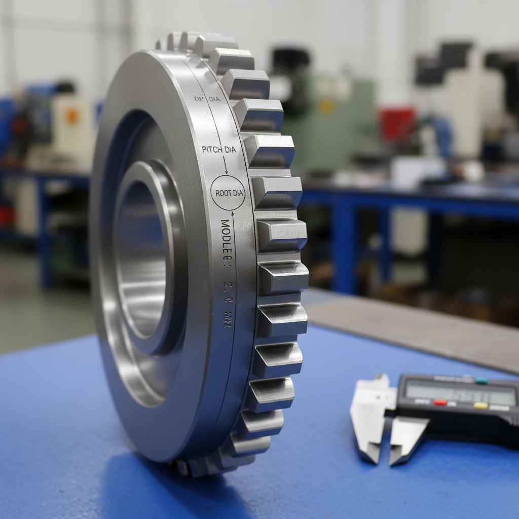
The fundamental definition utilized in spur gear module calculation is the ratio of the pitch diameter to the number of teeth, serving as the primary metric index for tooth size. A higher module value indicates a physically larger and mechanically stronger tooth, while a lower module represents finer teeth utilized for precision; this unit is typically expressed in millimeters (mm) and dictates compatibility. For detailed engineering standards, consult our About page.
Understanding the Module Concept
- The core concept:
- Module ($m$) represents the physical size of the tooth.
- It determines the distance between corresponding points on adjacent teeth.
- It is the metric equivalent of Diametral Pitch ($DP$) but inversely related.
- Here is the deal: If two gears have different modules, they simply cannot mesh.
The Role of Tooth Size
- Why size matters:
- Larger modules = Higher load capacity and bending strength.
- Smaller modules = Higher precision and smoother operation.
- Tooth height and thickness scale directly with the module.
- Key Takeaway: The module is the absolute DNA of the gear; it dictates every physical dimension of the tooth profile.
| Parameter | Symbol | Definition |
|---|---|---|
| Module | $m$ | Ratio of Pitch Diameter to Teeth ($d/z$) |
| Pitch Diameter | $d$ | Theoretical circle of rolling contact |
| Tooth Count | $z$ | Total integer number of teeth |
This table illustrates that the module is a derived value dependent on the fixed relationship between diameter and tooth count.
2. Which Formulas Are Essential for Accurate Spur Gear Module Calculation?
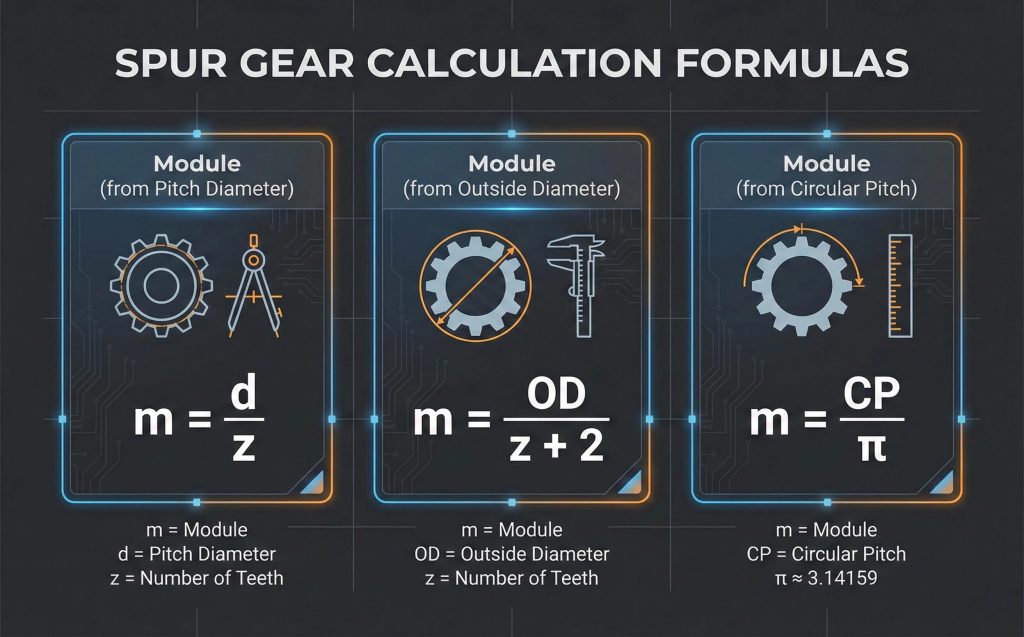
The most essential formula for spur gear module calculation is the pitch diameter ($d$) divided by the number of teeth ($z$), expressed as $m = d / z$. While this is the primary equation, derivative formulas involving the outside diameter ($OD$) or circular pitch ($CP$) are also frequently used when the pitch diameter is not directly measurable on the physical component.
Primary Metric Formula
- The standard equation:
- $m = d / z$ (Pitch Diameter ÷ Number of Teeth).
- $d = m \times z$ (To find Pitch Diameter).
- $z = d / m$ (To find Number of Teeth).
- You might be wondering: Can I calculate it without the pitch diameter? Yes, using the Outside Diameter ($OD$): $m = OD / (z + 2)$.
Calculating via Circular Pitch
- Alternative methods:
- Formula: $m = CP / \pi$.
- Useful when only the arc distance between teeth is known.
- Ensures accuracy when reverse-engineering worn gears.
- Key Takeaway: While $m = d / z$ is the standard design formula, $m = OD / (z + 2)$ is the practical formula for measuring existing gears.
| Formula Type | Equation | Application |
|---|---|---|
| Standard | $m = d / z$ | Designing new gears |
| Reverse Engineering | $m = OD / (z + 2)$ | Measuring physical parts |
| Circular Pitch | $m = CP / \pi$ | Rack and pinion calculation |
Using the correct formula based on available data is critical for avoiding expensive manufacturing errors.
3. How Do I Perform a Step-by-Step Spur Gear Module Calculation?
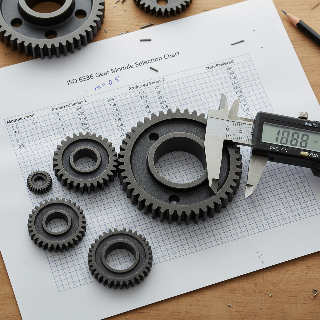
To perform a step-by-step spur gear module calculation, one must first accurately measure the outside diameter ($OD$) and then count the exact number of teeth on the gear. Once these variables are identified, apply the division formula to determine the module, and finally, round the result to the nearest standard ISO module value to ensure manufacturability.
Measuring Gear Dimensions
- Critical measurements:
- Identify the Outside Diameter ($OD$) using precision calipers.
- Count the total number of teeth ($z$) carefully.
- But here is the kicker: Direct measurement of the pitch circle is impossible; it is theoretical.
Applying the Calculation
- The process:
- Count teeth ($z$).
- Measure Outside Diameter ($OD$) in millimeters.
- Apply formula: $m = OD / (z + 2)$.
- Verify against standard module tables (e.g., 1, 1.5, 2, 3).
- Key Takeaway: Always round your calculated result to the nearest standard module, as wear or tolerances can cause slight deviations.
| Step | Action | Formula/Tool |
|---|---|---|
| 1 | Count Teeth | Visual / Marker |
| 2 | Measure OD | Calipers (mm) |
| 3 | Calculate | $m = OD / (z + 2)$ |
| 4 | Standardize | Round to ISO series |
This process ensures you identify the correct standard tool required for manufacturing the replacement gear.
4. How Does Spur Gear Module Calculation Differ Between Metric and Imperial?
Spur gear module calculation in the metric system uses the Module ($m$) defined by millimeters, whereas the imperial system uses Diametral Pitch ($DP$) defined by teeth per inch. These two systems are inversely related; as the module increases, the tooth size increases, but as the diametral pitch increases, the tooth size decreases.
Module vs. Diametral Pitch
- Key differences:
- Module ($m$): Ratio of Diameter to Teeth ($d/z$).
- Diametral Pitch ($DP$): Ratio of Teeth to Diameter ($z/d$).
- The catch: A Module 2 gear is much larger than a 2 Pitch gear.
Conversion Formulas
- Switching systems:
- $m = 25.4 / DP$
- $DP = 25.4 / m$
- Essential for integrating global components.
- Key Takeaway: Never assume a gear is metric or imperial; use conversion formulas to verify which system yields a whole number.
| Metric Module ($m$) | Approx. DP | Exact Conversion |
|---|---|---|
| 1.0 | 25.4 | 25.400 |
| 2.0 | 12.7 | 12.700 |
| 2.54 | 10.0 | 10.000 |
A calculated module of 2.54 mm strongly suggests the gear is actually an imperial 10 DP gear.
5. What Factors Influence the Results of Spur Gear Module Calculation?
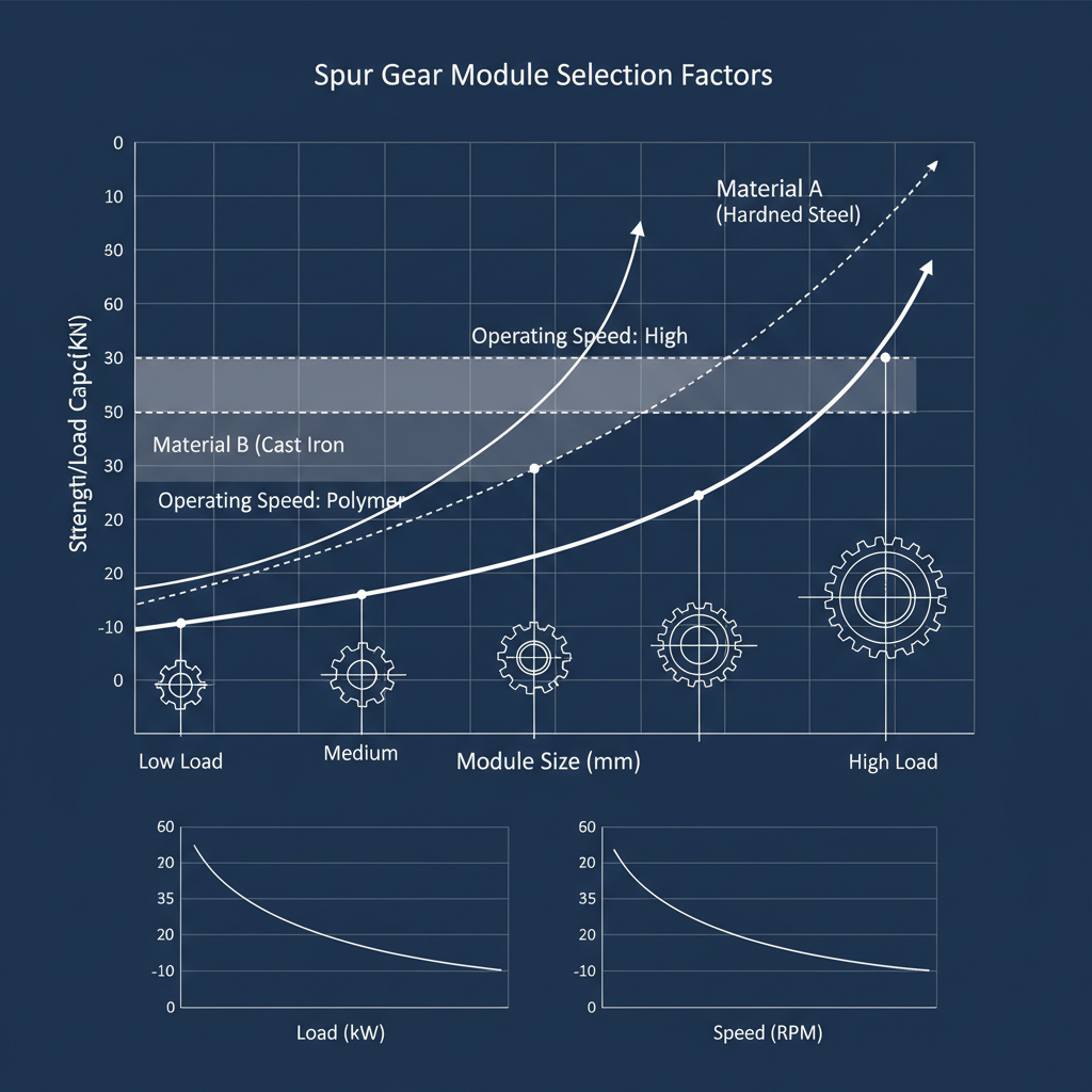
Factors influencing spur gear module calculation and selection include the required power transmission capacity, operating speed, and the physical material properties of the gear. Engineers must choose a module large enough to withstand bending stresses, yet small enough to run quietly; considering helical gear options may be necessary for noise reduction in high-speed applications.
Load and Speed Requirements
- Selection criteria:
- High Load: Requires larger modules for tooth strength.
- High Speed: Favors smaller modules for reduced noise.
- Balance: Optimizing for both durability and efficiency.
Material Considerations
- Material impact:
- Steel gears handle higher loads than plastic.
- Hardened alloys allow for smaller modules.
- Here is the truth: Material strength allows you to downsize the module.
- Key Takeaway: You must balance the physical strength of a large module against the smooth operation of a small module.
| Factor | Large Module Effect | Small Module Effect |
|---|---|---|
| Load Capacity | Increases | Decreases |
| Noise Level | Increases | Decreases |
| Precision | Decreases | Increases |
Selecting the right module is a trade-off between sheer strength and operational smoothness.
6. Why Is the Pitch Circle Diameter Critical to Spur Gear Module Calculation?
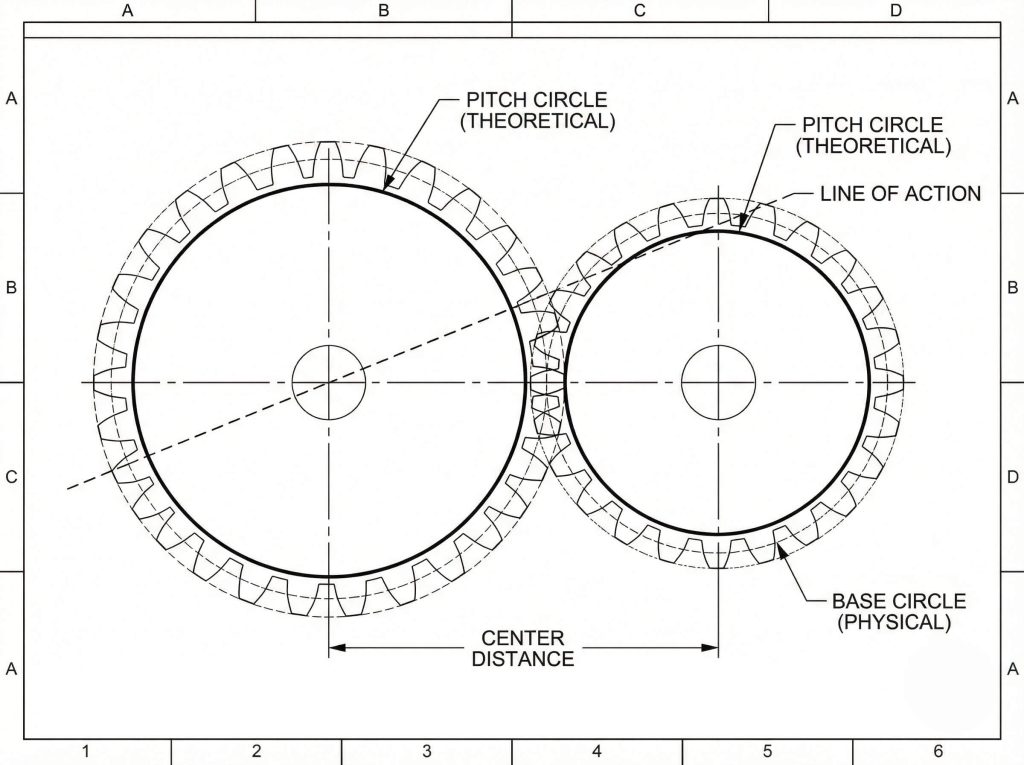
The pitch circle diameter is critical to spur gear module calculation because it represents the theoretical circle where rolling contact occurs without slippage. It serves as the reference dimension from which the module, pressure angle, and gear ratio are derived, making it the most significant geometric parameter in gear engineering.
Defining the Pitch Circle
- Theoretical basis:
- It is the imaginary circle where gears mesh.
- Determines the center distance between shafts.
- Think about this: Without the pitch circle, calculating speed ratios is impossible.
Impact on Mesh Geometry
- Geometric dependency:
- Tangential contact occurs here.
- Pressure angles are defined at this intersection.
- Directly dictates the velocity ratio.
- Key Takeaway: The pitch circle is the invisible foundation of gear geometry, defining exactly where and how gears engage.
| Dimension | Type | Formula Relation |
|---|---|---|
| Pitch Diameter | Theoretical | $d = m \times z$ |
| Outside Diameter | Physical | $OD = m(z+2)$ |
| Root Diameter | Physical | $RD = d – 2.5m$ |
You cannot measure pitch diameter directly; it must be calculated from physical dimensions.
7. How Do AGMA and ISO Standards Affect Spur Gear Module Calculation?
AGMA and ISO standards affect spur gear module calculation by establishing rigid guidelines for standard module series, tolerance classes, and tooth profiles to ensure global interchangeability. While ISO heavily utilizes the metric module system, AGMA standards often reference Diametral Pitch, though both provide conversion methodologies and quality grades for manufacturing.
ISO and DIN Specifications
- Global standards:
- ISO 54 defines standard module series (e.g., 1, 1.25, 1.5).
- DIN 780 aligns European manufacturing tolerances.
- Ensures off-the-shelf compatibility.
AGMA Classification Systems
- North American standards:
- Focuses on Diametral Pitch ($DP$).
- AGMA 2000-A88 defines accuracy grades.
- Why it matters: Dictates quality control and inspection methods.
- Key Takeaway: Adhering to ISO or AGMA standards ensures your calculated module corresponds to available cutting tools.
| Standard | System | Primary Unit |
|---|---|---|
| ISO | Metric | Module (mm) |
| DIN | Metric | Module (mm) |
| AGMA | Imperial | Diametral Pitch (1/in) |
Mixing standards typically leads to non-standard tooling requirements and increased costs.
8. How Does Spur Gear Module Calculation Impact Industrial Applications?
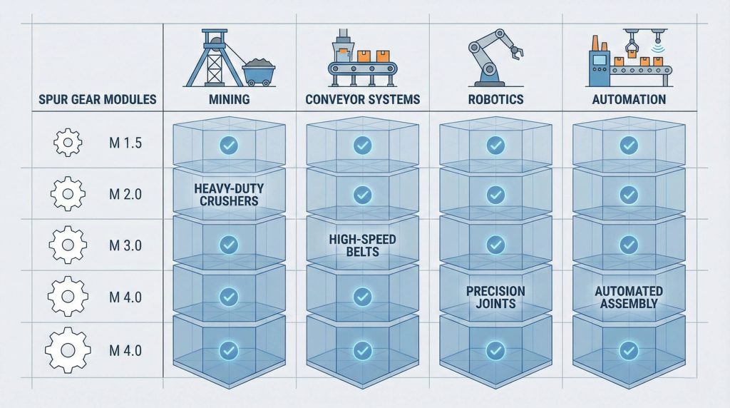
Spur gear module calculation directly impacts industrial applications by defining the torque capability and precision of machinery, ranging from heavy mining equipment to delicate medical devices. Spur gears are frequently paired with gear rack systems for linear motion, where the module determines both linear resolution and load capacity.
Heavy Industry vs. Precision
- Heavy-duty use:
- Mining conveyors (Large Modules > 6).
- Crushing equipment.
- High shock load resistance.
Robotics and Automation
- Fine-duty use:
- Robotic actuators (Small Modules < 1).
- Medical dosing pumps.
- It gets better: Small modules allow for compact, zero-backlash designs.
- Key Takeaway: The module scale dictates the application, from massive torque transmission to microscopic precision movement.
| Application | Typical Module | Requirement |
|---|---|---|
| Mining Crusher | Module 8+ | High Strength |
| Conveyor Belt | Module 3-5 | Durability |
| Robotic Arm | Module 0.5-1 | Precision |
Matching the module to the application load is the primary task of the design engineer.
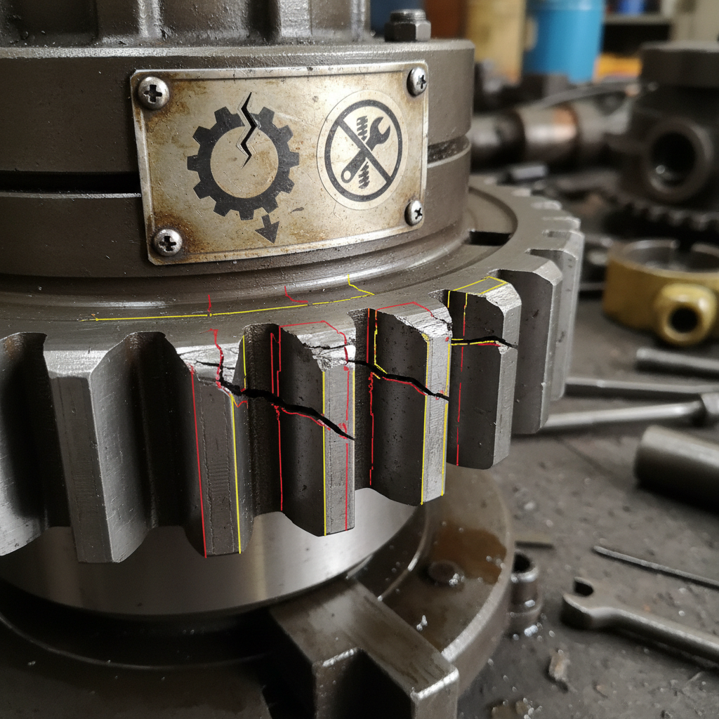
9. What Are the Common Mistakes to Avoid During Spur Gear Module Calculation?
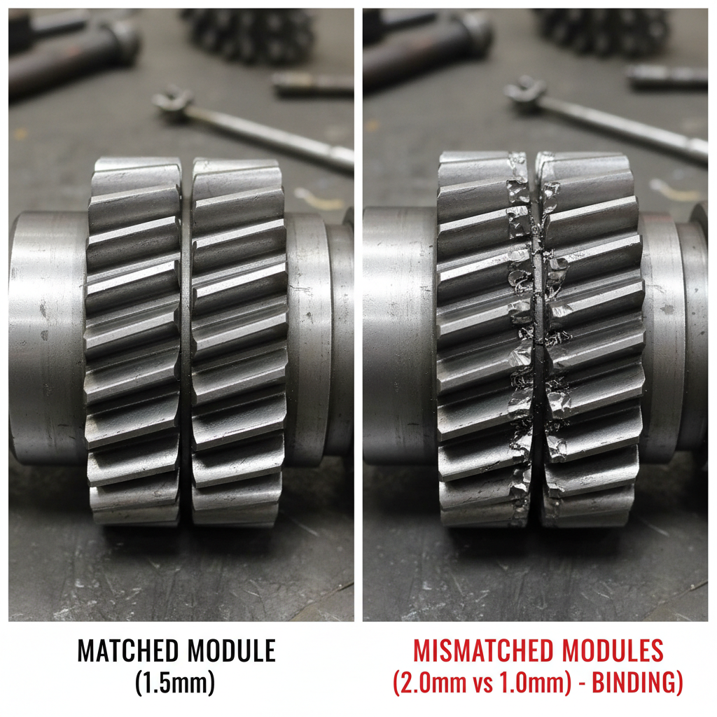
Common mistakes during spur gear module calculation include failing to round calculated values to standard module sizes and ignoring the impact of dynamic loads or shock factors. Additionally, attempting to mesh gears with slightly different modules or pressure angles leads to catastrophic interference and rapid wear.
Mismatched Module Errors
- Critical failures:
- Meshing Module 2 with Module 2.1 is impossible.
- Results in binding and noise.
- Bottom line: Modules must match exactly.
Undersizing for Load
- Strength oversight:
- Calculating for static load only.
- Ignoring startup torque spikes.
- Result: Broken teeth or stripped gears.
- Key Takeaway: Never approximate module sizes; a “close enough” module will destroy the gearbox.
| Error | Cause | Consequence |
|---|---|---|
| Mismatch | Mixing Imperial/Metric | Binding/Failure |
| Undersizing | Ignoring Shock Load | Broken Teeth |
| Rounding | Custom vs Standard | High Tooling Cost |
Precision in calculation prevents costly downtime and dangerous equipment failures.
10. How Does Spur Gear Module Calculation Relate to Addendum and Dedendum?
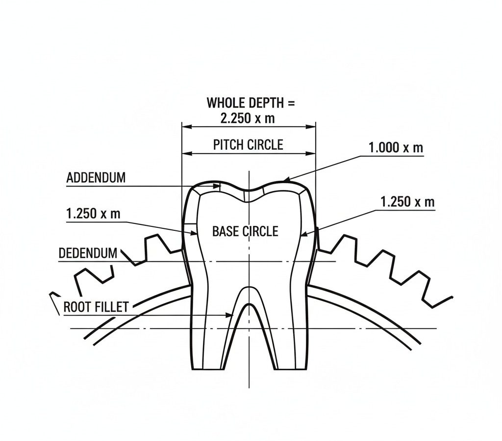
Spur gear module calculation is the foundation for determining the addendum (tooth height above the pitch circle) and dedendum (tooth depth below the pitch circle). Specifically, for standard gears, the addendum is equal to $1 \times m$, and the dedendum is typically $1.25 \times m$, meaning the entire tooth geometry scales linearly with the calculated module.
Calculating Addendum Heights
- Tooth top geometry:
- Formula: $h_a = 1.0 \times m$.
- Defines the outside diameter.
- Crucial for casing clearance.
Determining Whole Depth
- Total tooth size:
- Formula: $h = 2.25 \times m$ (Whole Depth).
- Includes clearance for lubrication.
- Key Takeaway: The module scales the entire tooth profile linearly; changing the module changes every vertical dimension of the tooth.
| Parameter | Formula (Metric) | Description |
|---|---|---|
| Addendum | $1.0 \times m$ | Height above pitch circle |
| Dedendum | $1.25 \times m$ | Depth below pitch circle |
| Whole Depth | $2.25 \times m$ | Total tooth height |
Understanding these proportions is essential for verifying if a gear is non-standard or profile shifted.
Conclusion
Accurate spur gear module calculation ($m=d/z$) is the foundation of reliable power transmission, ensuring component interchangeability and system performance. Correct identification ensures seamless maintenance, reduced noise, and extended equipment life by preventing the catastrophic failure associated with mismatched components. Don’t risk your machinery on guesswork; contact our engineering team at Yantong Tech to verify your calculations and manufacture the precise components you need.
FAQ
Can I calculate the module if I only have the center distance and ratio?
Yes, but it requires derivation. You can determine the module using the center distance ($a$) and the gear ratio ($i$). Since $a = m(z_1 + z_2) / 2$, you can solve for the specific tooth counts and module that fit your physical constraints, though you must ultimately select a standard integer tooth count.
What is the best way to distinguish between Module and Diametral Pitch?
The best method is to calculate both values from the physical dimensions. Calculate Module ($OD / (z+2)$) and Diametral Pitch ($(z+2) / OD$). Whichever result yields a whole number (or standard value like 1.5, 12.7) indicates the correct system; a result of “Module 3.175” is actually a “DP 8” gear.
How do I handle gears with an odd number of teeth when measuring?
When measuring the Outside Diameter ($OD$) of a gear with an odd number of teeth, calipers will not rest on opposite tooth tips. You must measure from a tooth tip to the opposite root and add the addendum height, or preferably use a specialized calculation involving the bore center to the tip radius to find the accurate OD.
Is module calculation different for helical gears?
Yes, it is slightly more complex. For helical gears, you must distinguish between the Normal Module ($m_n$) and the Transverse Module ($m_t$). The standard spur gear formula applies to the Transverse Module, but the Normal Module is what defines the cutter profile and is related by the cosine of the helix angle ($m_n = m_t \times \cos(\beta)$).
Why is my calculated module not a round number?
If your calculated module is not a standard value (like 2, 2.5, 3), the gear might be worn, measuring errors may have occurred, or it could be a “profile shifted” gear. Profile shifting modifies the Outside Diameter without changing the module, often confusing reverse engineering efforts; check the span measurement over multiple teeth to verify the true module.