1. Introduction
A self-locking mechanism in a worm gearbox is a physical state where the friction angle between the worm and gear exceeds the lead angle, preventing the load from back-driving the input shaft. While this definition seems straightforward, the engineering reality is far more complex and fraught with liability risks.
Here is the deal: Many engineers and procurement managers operate under the dangerous assumption that if a worm gearbox has a high reduction ratio (e.g., 60:1), it is automatically and permanently self-locking. This assumption is the leading cause of back-driving failures in lifting equipment, inclined conveyors, and safety-critical positioning systems.
But here is the kicker: Relying solely on theoretical self-locking without calculating the specific friction variables is a gamble. Imagine the consequence: A heavy load holds position during factory acceptance testing but fails six months later in the field. Why does this happen? As the gears “run in,” the surface roughness improves, the friction coefficient drops, and your “self-locking” brake vanishes. This leads to catastrophic equipment damage, safety recalls, and massive downtime costs that far exceed the price of the gearbox component.
The solution is to treat self-locking as a dynamic variable, not a fixed feature. In this guide, you will learn the physics behind the mechanism, why manufacturing precision impacts safety, and how to calculate safety factors. At Yantong Tech, we calculate the “running-in” friction drop during the design phase. We use precise gear grinding (ISO 1328 Grade 6) to ensure the friction remains predictable, and we recommend auxiliary brakes for critical safety applications.
2. What Defines the Self-Locking Mechanism in Worm Gear Systems?
Let’s get the facts straight.
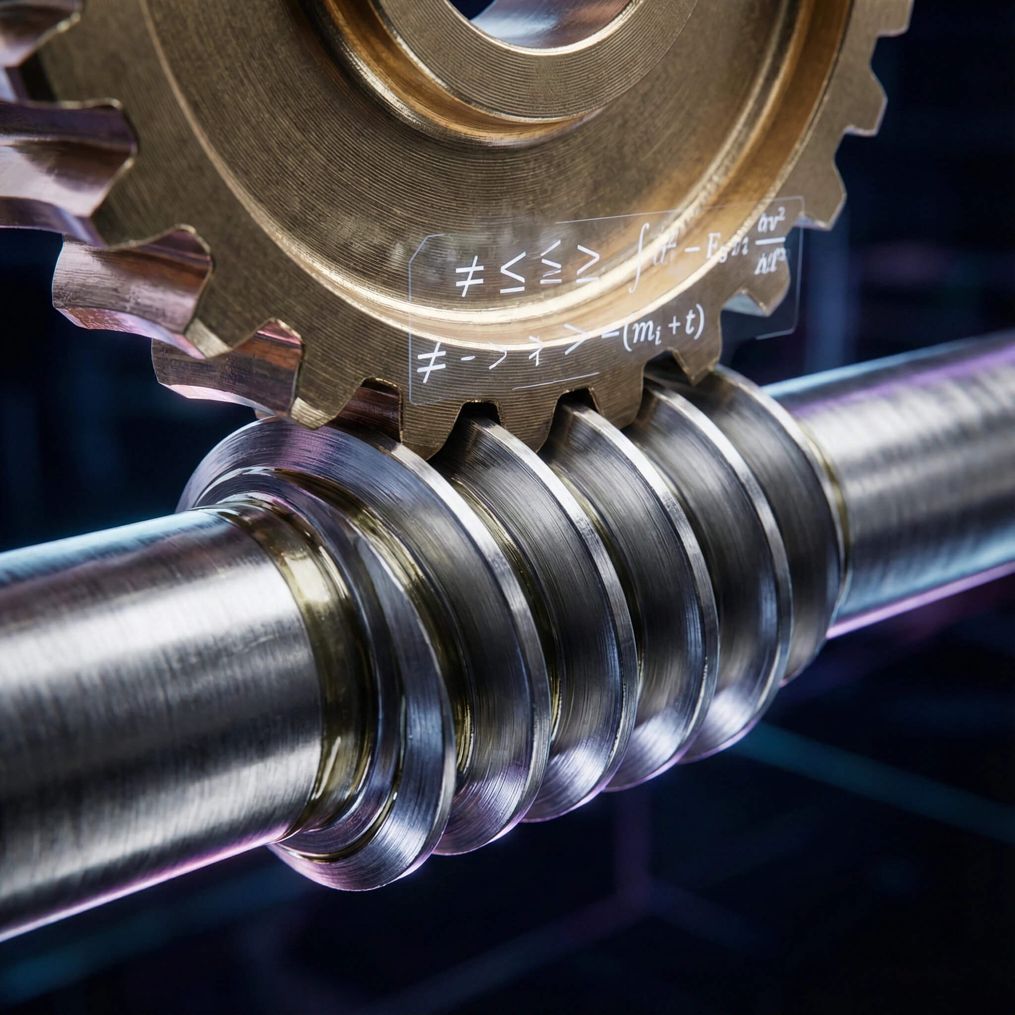
To interpret the self-locking mechanism correctly, you must look beyond the gear ratio and examine the relationship between the Lead Angle ($\gamma$) and the Friction Angle ($\rho$). Self-locking is not a magic switch inside the gearbox; it is a battle between forces.
How does the friction angle determine locking?
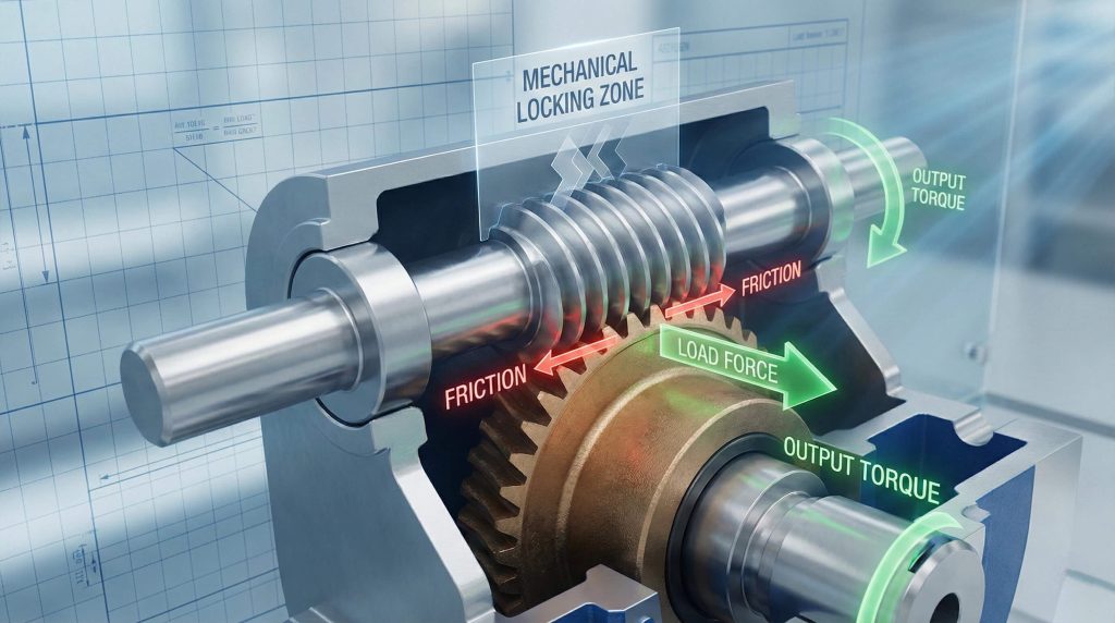
The core concept relies on a simple inequality: the system locks when the friction force resisting movement is greater than the force component of the load trying to rotate the worm. The Friction Angle ($\rho$) is a theoretical angle derived from the coefficient of friction ($\mu$) between the meshing teeth.
- Static vs. Dynamic Variables: The static friction coefficient (when the gears are stopped) is always higher than the dynamic friction coefficient (when the gears are moving). A gearbox might be self-locking when stopped but may fail to stop a load that is already in motion.
- The Golden Rule: The mathematical condition for self-locking is $\mu > \tan(\gamma)$. If the tangent of the lead angle is greater than the coefficient of friction, the gear will back-drive.
- Self-Locking vs. “Hard to Back-Drive”: There is a distinct difference between true self-locking and high resistance. A gearbox with a lead angle of 6 degrees might be difficult to turn by hand (hard to back-drive) but will eventually slip under a heavy industrial load.
Is self-locking synonymous with irreversibility?
You might be wondering if “irreversibility” guarantees safety. Ideally, yes, but in practice, absolute irreversibility is a theoretical concept. Self-locking is conditional.
- External energy enters the system in forms you might not anticipate. Heavy vibration, shock loads, or temperature spikes can momentarily lower the friction coefficient.
- Once that friction threshold is breached, the “lock” is broken, and gravity takes over.
Key Takeaway: You cannot treat self-locking as a binary feature (on/off); it is a dynamic state dependent on physical variables. Always calculate for the worst-case scenario (dynamic friction) rather than the best-case (static friction).
3. How to Calculate the Self-Locking Capability?
You might be wondering how to verify this on your prints.
When you review a gearbox specification from Yantong Tech or any other manufacturer, you need to look specifically for the Lead Angle (sometimes called the Helix Angle). This is the angle of the worm thread inclination relative to a plane perpendicular to the worm axis.
What is the formula for the self-locking condition?
The fundamental formula required to verify your design safety is:
$$ \mu > \tan(\gamma) $$
Where:
- $\mu$ (mu) = The static coefficient of friction between the worm and the gear wheel.
- $\gamma$ (gamma) = The lead angle of the worm.
For example, if you have a standard steel-on-bronze worm gear set, the static coefficient of friction is typically around 0.15. The arctangent of 0.15 is approximately 8.5 degrees. Therefore, theoretically, any worm with a lead angle less than 8.5 degrees should be statically self-locking. However, Yantong Tech engineers apply a significant safety factor because friction drops as the gearbox warms up.
How does the lead angle influence the outcome?
The lead angle is the single most critical geometric factor. A high-ratio gearbox (e.g., 100:1) usually has a single-start worm with a very low lead angle, making it highly secure. A low-ratio gearbox (e.g., 5:1) often uses a 4-start worm with a high lead angle, making it fully reversible.
Table 1: Lead Angle vs. Self-Locking Probability
| Lead Angle ($\gamma$) | Static Self-Locking | Dynamic Self-Locking | Risk Level |
|---|---|---|---|
| < 3° | Certain | High Probability | Low: Safe for holding loads (Static). |
| 3° – 5° | Likely | Uncertain | Medium: May creep under vibration. |
| 5° – 8° | Possible | Unlikely | High: Requires external brake. |
| > 8° | None | None | Critical: Will back-drive freely. |
Yantong Tech Expert Analysis:
“For applications requiring static holding power without an external brake, Yantong Tech engineers recommend a lead angle strictly below 3 degrees. While theoretical locking happens up to 8 degrees, manufacturing tolerances and surface polishing can reduce friction unexpectedly. We design single-start worms specifically to keep this angle low for safety-critical clients in the hoisting industry.”
It gets better: Single-start worms are superior for self-locking because they naturally possess the lowest lead angles. If your design requires a multi-start worm for speed, you are almost certainly sacrificing the self-locking capability.
Key Takeaway: If your lead angle exceeds 5 degrees, you are relying on luck, not physics. Keep the angle low for security, and verify the “start count” of the worm shaft.
4. Why Does the Self-Locking Mechanism Fail?
Here is the deal regarding failure modes.
Even if your calculations show that $\mu > \tan(\gamma)$, real-world operating environments are rarely ideal. External factors can alter the physics inside the housing, turning a safe machine into a hazard.
Can vibration neutralize the self-locking effect?
Vibration is the enemy of friction. When a static load is subjected to vibration (e.g., a conveyor belt motor humming nearby, or a hoist operating on a vibrating platform), the contact between the gear teeth micro-slips.
- This micro-movement transitions the system from Static Friction to Dynamic Friction.
- Since dynamic friction is significantly lower than static friction (often by 30-40%), the resisting force drops.
- Once the resistance drops below the lead angle’s threshold, the load begins to accelerate downward.
How does lubrication alter the friction coefficient?
Lubrication is necessary to prevent wear, but “better” lubrication can actually disable your self-locking mechanism. High-performance synthetic oils are designed to be slippery—reducing friction to improve efficiency and lower temperatures.
Table 2: Impact of Lubricant Type on Friction Coefficient
| Lubricant Type | Viscosity Index | Friction Coefficient ($\mu$) | Self-Locking Impact |
|---|---|---|---|
| Mineral Oil (Standard) | Medium | ~0.15 (Static) | High: Supports locking. |
| Polyglycol (Synthetic) | High | ~0.09 – 0.11 (Static) | Reduced: Risk of slippage. |
| High-Temp Additives | Very High | < 0.08 (Static) | Disabled: Likely to back-drive. |
Yantong Tech Expert Analysis:
“We frequently see engineers upgrade to expensive synthetic oils to extend the service interval, only to find their hoists start drifting. While synthetic oil extends gear life, it reduces the friction coefficient by up to 30%, potentially disabling the self-locking feature in borderline designs. At Yantong Tech, we specify the exact lubricant viscosity on the nameplate to ensure the friction physics remain within the design parameters.”
Key Takeaway: External factors like vibration and slick synthetic oils can turn a self-locking worm gear into a back-driving hazard. Never change lubricant specifications without recalculating your safety factors.
5. How Material Choice Impacts Self-Locking Reliability
This is where quality manufacturing counts.
The “Coefficient of Friction” ($\mu$) is not a random number; it is a result of the tribological interaction between two specific materials. You cannot achieve reliable self-locking with inconsistent materials.
Why is the Bronze-on-Steel pairing critical?
The industry standard for worm gears is a hardened steel worm shaft paired with a bronze worm wheel.
- The Worm: Yantong Tech utilizes 20CrMnTi alloy steel, carburized and quenched to a hardness of 58–62 HRC. This extreme hardness ensures the worm thread does not deform under load.
- The Wheel: We pair this with ZCuSn10Pb1 (Tin Bronze).
- The Physics: This specific metallurgical combination generates a predictable, stable friction coefficient of 0.15 (static). If a manufacturer substitutes the wheel with Cast Iron or Aluminum Bronze to save costs, the friction coefficient becomes erratic. Aluminum Bronze, while stronger, has a lower friction coefficient (slipperier) and is more prone to seizing (galling) under high heat, which can cause catastrophic lock-up rather than controlled self-locking.
Does surface roughness affect the friction angle?
But wait, there is more. The surface finish of the gear teeth dictates how the oil film behaves.
Table 3: Surface Roughness vs. Friction Coefficient
| Manufacturing Process | Surface Roughness (Ra) | Friction Stability | Efficiency |
|---|---|---|---|
| Hobbing (Standard) | 1.6 – 3.2 $\mu m$ | High (Rough) | Low |
| Yantong Precision Grinding | 0.4 – 0.8 $\mu m$ | Predictable | Optimized |
| Mirror Polishing | < 0.2 $\mu m$ | Too Low (Slippery) | High |
Yantong Tech Expert Analysis:
“Yantong Tech utilizes ISO 1328 Grade 6 precision grinding for our worm shafts. While smoother gears are generally more efficient, there is a limit. If the surface is ‘mirror polished,’ the oil film becomes too effective, and friction drops too low for self-locking. We control the surface roughness to a specific Ra value that balances efficiency with the necessary friction angle for safety.”
Key Takeaway: Material consistency ensures friction consistency. Cheap materials and uncontrolled surface finishes lead to unpredictable holding forces.
6. Where Should You Apply Self-Locking Worm Gears?
Think about your application context.
Understanding where to rely on self-locking is just as important as understanding how it works. It is a feature best used for position holding in non-critical scenarios or as a backup in critical ones.
Which industries rely on this mechanism?
- Vertical Lifts and Hoists: Used as a secondary safety backup to the primary brake. If the motor brake fails, the gearbox prevents free-fall.
- Inclined Conveyors: Prevents the belt from rolling backward when the power is cut, protecting the product and workers at the bottom of the incline.
- Solar Trackers: Holds the solar panels in position against wind loads without consuming power to fight the wind.
- Theatre Stage Rigging: essential for holding scenery in place silently without the “click-clack” of a ratchet or the hum of a motor brake.
When is an external brake mandatory?
Here is the bottom line: If human safety is at risk, self-locking is never sufficient on its own.
- The Rule: European and American safety standards (such as EN 81 for elevators) mandate that any lifting device carrying personnel must have a redundant mechanical braking system.
- Yantong’s Stance: We advise all clients designing elevators, man-lifts, or overhead cranes to install a fail-safe electromagnetic brake on the rear of the motor. The worm gear’s self-locking capability should be viewed as a “last line of defense,” not the primary safety device.
Key Takeaway: Use self-locking worm gears for efficiency and cost reduction in material handling, but never use it as the sole safety device for lifting people.
7. The Trade-Off: Efficiency vs. Self-Locking
But there is a price to pay.
In engineering, you rarely get something for nothing. The self-locking mechanism is inherently tied to efficiency—specifically, the lack of it.
Why does high efficiency kill self-locking?
The physics is a paradox:
- To lock the gear, you need high friction.
- To have high efficiency, you need low friction.
- Therefore, a self-locking gearbox must be inefficient.
A gearbox that is statically self-locking generally has an efficiency of less than 50%. This means that more than half of your motor’s power is being converted into heat rather than torque. If you require a gearbox with 90% efficiency, it will have a high lead angle and will back-drive instantly.
How do we manage the generated heat?
Since low efficiency equals high heat generation, self-locking gearboxes are prone to overheating.
- Oversizing: You may need to select a larger gearbox size not for torque, but to provide more surface area for heat dissipation.
- Cooling Fins: Yantong casings are cast with optimized cooling fins to maximize airflow.
- Lubrication: Using a high-viscosity mineral oil helps maintain the oil film under high-temperature/high-friction conditions associated with self-locking gears.
Key Takeaway: You must choose between high efficiency or self-locking capabilities; you cannot maximize both in the same gear set. Expect to size up your motor to compensate for the efficiency loss in a self-locking design.
8. Conclusion
We have established that self-locking is a function of the lead angle (typically $<3^\circ$ for security) and the friction coefficient, not merely the gear ratio. It is a calculated, dynamic variable that can be compromised by vibration, synthetic lubrication, and wear over time.
True reliability requires physics, not guesswork.
At Yantong Tech, we don’t just cut gears; we engineer transmission reliability. By controlling the material hardness (HRC 58-62) and strictly verifying the tooth surface profile with CMM inspection, we ensure the friction physics align with your safety calculations. We provide the precise Ra values and lead angle data you need to simulate real-world performance before you build your prototype.
Do not leave your safety factors to chance.
True self-locking requires precise geometry and controlled surface roughness. Contact Yantong Tech’s engineering team today to review your load parameters and verify your transmission calculations before freezing your design.
9. Frequently Asked Questions
Q1: Can I rely on self-locking for lifting human loads?
Judgment: Absolutely not.
Explanation: While self-locking prevents back-driving under static loads, vibration, shock, or wear can cause it to slip. Safety regulations (like ISO and AGMA standards) mandate a redundant mechanical brake for any application involving human safety.
Q2: Does the self-locking mechanism work in reverse?
Judgment: No, it is directional.
Explanation: Self-locking prevents the output (wheel) from driving the input (worm). The input shaft can always drive the output shaft, provided the motor has sufficient torque to overcome the friction and efficiency loss.
Q3: How does synthetic oil affect self-locking?
Judgment: It significantly reduces it.
Explanation: Synthetic oils have lower friction coefficients to improve efficiency. If your design relies on borderline friction to lock, switching to synthetic oil might cause the load to back-drive. Always consult Yantong engineers before changing lubrication specs.
Q4: Is a 50:1 ratio always self-locking?
Judgment: Not always.
Explanation: While high ratios usually have low lead angles, a 50:1 ratio with a multi-start worm or an exceptionally smooth surface finish might not lock. You must calculate based on the lead angle, not just the ratio.
Q5: What is the difference between static and dynamic self-locking?
Judgment: Static holds; dynamic stops.
Explanation: Static self-locking means the load won’t start moving from a dead stop. Dynamic self-locking means if the load is moving and power is cut, the friction is high enough to bring it to a stop. Static locking is common; dynamic locking is rare and difficult to achieve reliably.