
Many mechanical engineers struggle with premature failure in complex gear assemblies because of minor calculation errors in tooth geometry. This specific issue usually arises when someone fails to account for normal versus radial system differences in high-torque environments, leading to excessive noise. By implementing a standardized helical gear design procedure, you can ensure every component meets exact tolerances for long-term industrial reliability.
What is the standard helical gear design procedure?

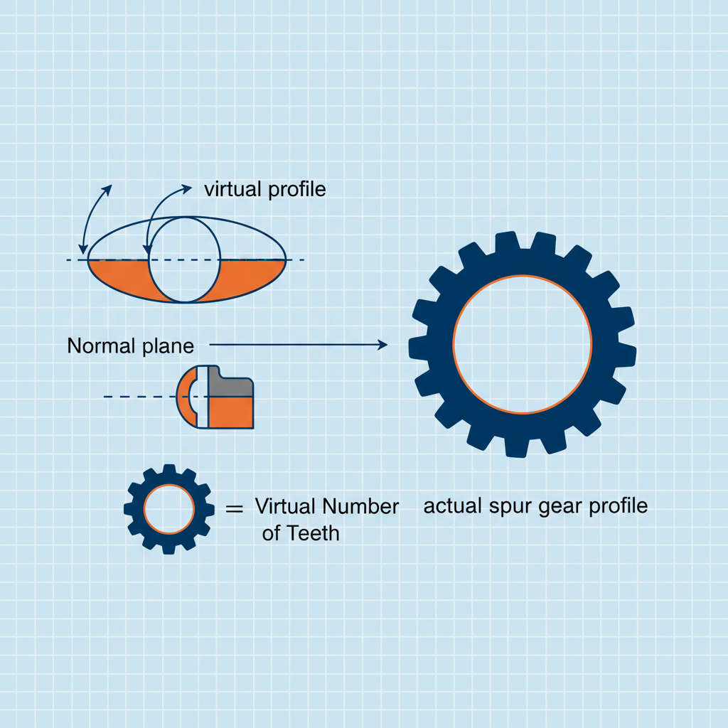
The standard helical gear design procedure involves defining tooth geometry in the normal system to ensure compatibility with standard manufacturing tools. This approach calculates dimensions perpendicular to the tooth flank, which mirrors spur gear dynamics. It is the most common method for ensuring efficient production in metric environments.
Normal System Advantages
Engineers prefer the normal system because it allow for the use of standard hobs and cutters across various helix angles. Here’s the deal… using standard tools reduces lead times and costs significantly. This method is vital for following technical specifications in high-volume production.
- Normal module provides the base for tooth sizing.
- Standard pressure angles ensure tool compatibility.
- Profile shifting is applied to adjust center distances.
| Normal Parameter | Formula / Metric | Design Impact |
|---|---|---|
| Reference Diameter | d = (z * mn) / cos(beta) | Determines basic size |
| Transverse Angle | tan(at) = tan(an) / cos(beta) | Affects mesh smoothness |
| Module Selection | mn (Standard Metric) | Tooling availability |
Key Takeaway: The normal system simplifies manufacturing by utilizing standard tooling while maintaining custom performance metrics.
Why use a radial helical gear design procedure?
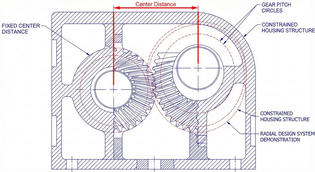
A radial helical gear design procedure focuses on the plane perpendicular to the gear axis to simplify parallel shaft housing calculations. This system is essential when designers need to match specific center distances without changing existing housing dimensions. It directly relates the pitch diameter to the circular pitch of the gear teeth.
Transverse Plane Precision
Working in the transverse plane allows for direct control over the contact ratio and pressure angles. But wait, there’s more… this approach makes it easier to optimize the helix angle for compact gearbox footprints. Many high-precision helical gears utilize this system for better spatial integration.
- Direct pitch calculations for shaft centers.
- Easier integration with spur gear-based housings.
- Enhanced control over transverse contact ratios.
| Radial Attribute | Technical Advantage | System Integration |
|---|---|---|
| Transverse Pitch | pt = pi * mt | Direct shaft spacing |
| Profile Shift | Radial x-coefficient | Backlash control |
| Tooling Link | Requires mt adjustment | Custom cutter offset |
Key Takeaway: Designing in the radial system provides the most intuitive path for engineers focused on physical layout and assembly constraints.
How does the Sunderland helical gear design procedure work?
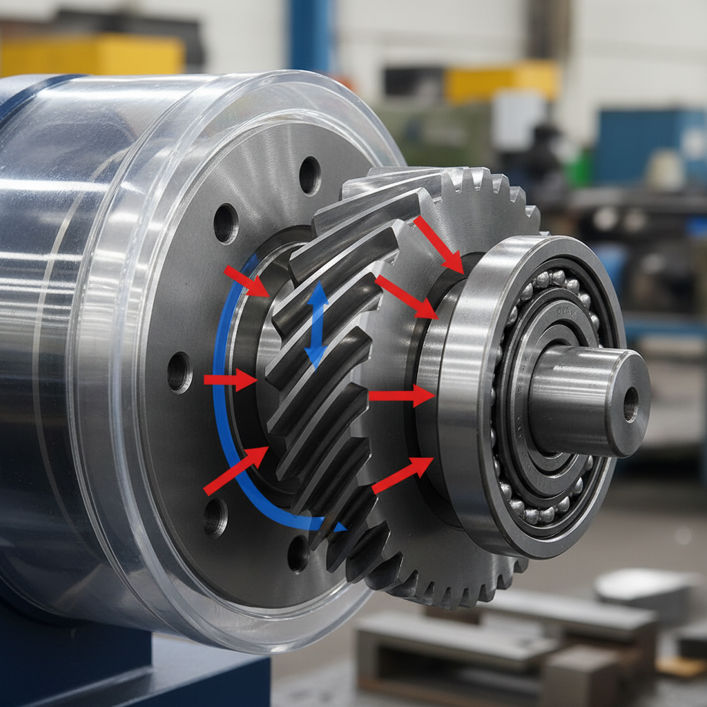
The Sunderland helical gear design procedure utilizes a fixed helix angle of 22.5 degrees specifically for double helical or herringbone gear profiles. These gears are famous for cancelling out axial thrust, which makes them ideal for massive power transmission. This method is a non-negotiable requirement for precision manufacturing in mining and heavy industrial sectors.
Herringbone Design Excellence
Sunderland gears utilize a specific radial pressure angle of 20 degrees to ensure consistent engagement across massive face widths. Ready for the good part? The secret lies in the simultaneous engagement of opposing helixes that stabilize the gear on its shaft. This eliminates the need for heavy-duty thrust bearings in many applications.
- Fixed helix angles simplify high-torque design.
- Axial thrust is naturally eliminated.
- Whole depth calculations follow unique standards.
| Sunderland Detail | Metric Value | Design Benefit |
|---|---|---|
| Helix Angle | 22.5 Degrees | Balanced thrust load |
| Pressure Angle | 20 Degrees (Radial) | Smooth power flow |
| Tooth Pattern | Double Helical | Internal force cancellation |
Key Takeaway: Sunderland gears provide the highest torque density while naturally eliminating parasitic axial forces that shorten bearing lifespan.
When is a rack-based helical gear design procedure needed?
A rack-based helical gear design procedure is required when converting rotary motion into linear travel with high precision and low noise. This setup provides exceptionally smooth linear motion compared to straight-cut versions because multiple teeth are always in partial engagement. You should select this for CNC machinery or automated positioning systems that require custom gear racks.
Linear Motion Synchronization
To achieve perfect linear displacement, you must align the helix angle of the gear with the opposite hand on the rack. This is where it gets interesting… you can choose specific angles that result in integer displacement values per revolution. This makes digital control much simpler for industrial robotics.
- Helical racks reduce mechanical vibration.
- Higher load capacity than spur racks.
- Smooth engagement for high-speed travel.
| Rack Component | Formula | Control Metric |
|---|---|---|
| Linear Pitch | cp = pi * mn / cos(beta) | Travel per tooth |
| Displacement | L = cp * z | Travel per revolution |
| Mounting Angle | Must match gear helix | Alignment accuracy |
Key Takeaway: Helical rack systems offer the best combination of precision, load capacity, and quiet operation for heavy-duty automation.
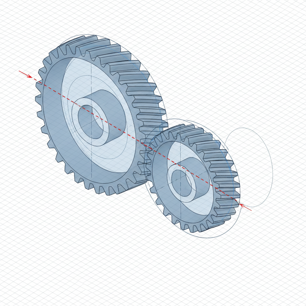
Does a crossed helical gear design procedure affect load?
A crossed helical gear design procedure significantly impacts load capacity because the gears operate on point contact rather than line contact. This unique configuration connects non-parallel, non-intersecting shafts where helix angles and hands can vary. You must ensure the sum of the helix angles matches the intended shaft angle to achieve proper engagement.
Point Contact Limitations
Because these gears do not share a line of contact, they are generally reserved for motion transmission rather than high-torque tasks. What’s the real story? While they offer unmatched design agility, the high sliding friction requires critical lubrication management to prevent wear. They are perfect for secondary drive systems with tight space constraints.
- Velocity ratio depends only on tooth count.
- Shaft angles are usually fixed at 90 degrees.
- Lubrication is critical due to sliding friction.
| Screw Gear Factor | Requirement | Operational Impact |
|---|---|---|
| Module Match | Must use same Normal Module | Fundamental mesh rule |
| Hand of Gear | Can be same or opposite | Determines rotation direction |
| Load Limit | Low to Medium Torque | Risk of surface pitting |
Key Takeaway: Screw gears provide high design flexibility for light-load applications provided you account for inherent surface stresses.
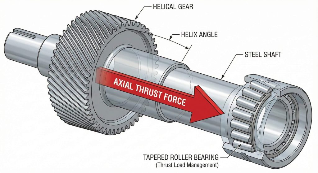
Can thrust impact the helical gear design procedure?
A professional helical gear design procedure accounts for axial thrust to prevent premature bearing failure and gearbox overheating. Managing this thrust is critical because the angled teeth naturally push the gear along the shaft during operation. You must evaluate the magnitude of this force based on the tangent of the helix angle.
Bearing Selection Strategies
The direction of the thrust depends on both the gear’s hand and its direction of rotation. You might be wondering… if your helix angle exceeds 20 degrees, you must utilize specialized thrust bearings to maintain stability. Failing to do so will destroy the internal seals and lead to mechanical breakage.
- Thrust bearings prevent axial shaft movement.
- Higher helix angles increase axial force.
- Heat generation increases with unmanaged thrust.
| Thrust Variable | Relationship | Mitigation Strategy |
|---|---|---|
| Helix Angle | Higher angle = Higher thrust | Use smaller angles for high load |
| Direction | Depends on Hand & Rotation | Orient bearings appropriately |
| Bearing Type | Needs axial load rating | Tapered roller or angular contact |
Key Takeaway: Proactively addressing axial loads through proper bearing selection is vital for ensuring long-term mechanical integrity.
How does bevel gearing use the helical gear design procedure?
Bevel gearing utilizes a specialized helical gear design procedure where tooth elements are tapered and converge at a central apex point. This allows for power transmission between intersecting shafts, with spiral variants offering the same smooth engagement found in helical sets. You must calculate the dimensions at the outer end to maintain consistency in manufacturing.
Pitch Cone Intersection
The most critical factor here is ensuring that the pitch cone apexes of both gears meet exactly at the intersection. Here’s the kicker… any misalignment will cause uneven loading and rapid failure of the gear teeth under industrial stress. These gears are highly sensitive to mounting distances in precision-machined housings.
- Velocity ratio uses the sine of pitch angles.
- Teeth are tapered toward the center apex.
- Spiral bevels offer higher speed ratings.
| Bevel Gear Type | Best Use Case | Performance Metric |
|---|---|---|
| Straight Bevel | Low speed, high torque | Simple manufacturing |
| Spiral Bevel | High speed, quiet operation | Superior load distribution |
| Zerol Bevel | Precision motion control | Zero spiral angle benefits |
Key Takeaway: Bevel gear accuracy depends entirely on the geometric precision of the pitch cone intersection and shaft alignment.
Why does Gleason aid the helical gear design procedure?
The Gleason helical gear design procedure introduces profile shifting and crowning to balance tooth strength and accommodate assembly misalignments. By applying a positive shift to the pinion, this system prevents undercutting and improves the overall contact ratio. It is the industry standard for producing robust gears for heavy-duty machinery.
Crowning for Robustness
Standard gears often suffer from edge loading if the shaft flexes, but Gleason-cut gears localize contact in the center. Think about it… this localized contact makes the entire assembly more robust against the minor misalignments found in agricultural tools. It ensures that the top clearance remains parallel along the entire tooth length.
- Profile shifting balances root strength.
- Crowning prevents catastrophic edge wear.
- Parallel clearance improves lubrication flow.
| Gleason Benefit | Technical Explanation | Maintenance Impact |
|---|---|---|
| Balanced Strength | Prevents pinion tooth breakage | Longer service intervals |
| Surface Crowning | Compensates for housing flex | Reduced noise and vibration |
| Depth Control | Standardized tool pathing | Easier replacement sourcing |
Key Takeaway: The Gleason system creates robust bevel gears that survive the harshest environments by centering the load distribution.
What is the spiral helical gear design procedure?
The spiral helical gear design procedure involves defining a central spiral angle to ensure that tooth engagement is gradual and quiet. These gears combine intersecting shaft transmission with helical geometry, making them ideal for high-speed automotive and aerospace applications. You must match the hands of the gears—one left and one right—to ensure they mesh correctly.
Gradual Tooth Engagement
Spiral bevel gears are cut using specialized circular face-mill cutters that create a localized contact area for maximum durability. Look closer… because they belong to a stub gear system, they are particularly effective for larger modules in heavy machinery. This design reduces impact noise and vibration even at extremely high velocities.
- Circular face-mill cutters create curved teeth.
- Higher load capacity than straight bevels.
- Reduced impact noise at high velocities.
| Spiral Detail | Industrial Application | Benefit |
|---|---|---|
| Spiral Angle | 35 Degrees (Typical) | Maximum overlap |
| Cutter Type | Circular Face-Mill | Specialized finish |
| Hand Pattern | Opposite for mesh | Required for 90° drives |
Key Takeaway: Spiral bevel gears provide the precision needed for high-speed systems where noise reduction is a critical design constraint.
How to optimize the helical gear design procedure?
To optimize the helical gear design procedure, you must focus on material efficiency and standardized metric modules to reduce production overhead. Precision in the initial design phase prevents expensive recalls and field repairs that can damage a manufacturer’s reputation. You can deliver gears with optimized contact ratios that build long-term trust in the marketplace.
Scalable Manufacturing Logic
Using digital design tools and standardized tables allows for rapid prototyping and faster time-to-market for new systems. The deal is… that a refined approach reduces material waste and minimizes the time required for secondary finishing operations. This leads to a better ROI for both the manufacturer and the end-user.
- Reduced material waste via precise sizing.
- Lower manufacturing costs through optimization.
- Higher ROI for end-users via durability.
| Optimization Focus | Method | B2B Benefit |
|---|---|---|
| Load Capacity | Profile Shifting | Smaller, lighter gearboxes |
| Noise Reduction | Spiral/Helical Geometry | Better operator environments |
| Durability | Crowning/Localized Contact | Lower total cost of ownership |
Key Takeaway: A rigorous and standardized design process is the only way to guarantee the high-quality components demanded by modern B2B clients.
Frequently Asked Questions
Q1: Can I use standard spur gear hobs for helical gears?
Yes, by using the normal system, you can utilize standard spur gear hobs by tilting the machine head to the required helix angle.
Q2: What’s the best way to manage high axial thrust?
The best solution is to install tapered roller bearings or angular contact bearings that are rated for combined radial and axial loads.
Q3: How do I know if the radial or normal system is better?
You should use the normal system for tool compatibility and the radial system when designing for a specific, pre-determined center distance.
Q4: Can I change center distances easily in a gear set?
Yes, by applying profile shifting or adjusting the helix angle, you can modify center distances without changing the number of teeth.
Q5: What’s the best system for noise reduction?
Helical and spiral bevel gears are the best options because their gradual tooth engagement significantly reduces vibration and mechanical noise.
Conclusion
In summary, mastering the complexities of metric gear technology—from normal helical calculations to specialized Gleason bevel designs—is essential for professional engineering. We have explored how profile shifting, thrust management, and proper system selection can significantly impact the performance of your mechanical assemblies. By following a structured helical gear design procedure, you eliminate guesswork and ensure your clients receive the highest quality components. If you are ready to elevate your manufacturing standards or need custom gear solutions, please contact us today to discuss your next project with our technical experts.