
Helical gear calculations, crossed helical gear meshes, and bevel gearing represent critical mathematical frameworks for designing durable transmission systems in modern industrial machinery. Engineers often face significant hurdles when attempting to synchronize complex gear geometries which leads to excessive noise or mechanical interference during operation. Here is the deal. Utilizing a precise helical gear cutting formula allows manufacturing teams to eliminate guesswork plus achieve perfect tooth engagement every single time. This technical documentation provides a robust foundation for calculating profile shifts plus optimizing mesh characteristics for high-performance B2B equipment.
How do you apply a helical gear cutting formula in the normal system?
Calculating a profile shifted helical gear within the normal system requires determining the working pitch diameter plus the working pressure angle specifically along the axial plane. This mathematical approach mirrors spur gear logic because helical gears effectively function like standard gears when viewed from their transverse section. Ready for the good part? Proper alignment ensures that the tooth thickness stays consistent throughout the entire manufacturing run across various batches of raw steel.
Precise Normal System Parameters
What is the real story?
- Working pitch diameters utilize normal modules.
- Profile shift coefficients modify tooth thickness.
- Axial pressure angles depend on helix angles.
- Center distances remain fixed after shift adjustments.
Key Takeaway: Normal system calculations provide the necessary geometric data for hobbing machines to produce accurate tooth profiles without interference.
| Parameter | Symbol | Calculation Logic |
|---|---|---|
| Normal Module | m_n | Standardized base value |
| Helix Angle | beta | Determines tooth twist |
| Center Distance | a_x | Distance between gear centers |
This data structure allows technicians to input variables into CNC controllers with absolute confidence during the primary helical gear production cycle.
Why does a helical gear cutting formula matter for radial systems?
Radial system calculations prioritize the transverse plane which directly influences how gears interact within a compact gearbox housing under heavy torque loads. Transforming dimensions between normal plus radial systems requires trigonometric functions that account for the specific helix angle chosen for the application. This is where it gets interesting. Using a radial helical gear cutting formula ensures that the transverse module matches the physical constraints of the existing machine assembly perfectly.
Radial System Conversion Steps
But here is the kicker.
- Transverse modules derive from normal modules.
- Radial pressure angles increase with helix tilt.
- Standard gears require zero profile shift coefficients.
- Pitch diameters link directly to tooth counts.
Key Takeaway: Radial systems simplify the design process for engineers focusing on center distance constraints within fixed industrial gearboxes.
| System Component | Metric Unit | Technical Requirement |
|---|---|---|
| Transverse Pitch | p_t | Must align with rack |
| Pressure Angle | alpha_t | Measured on radial plane |
| Addendum | h_a | Gear tooth tip height |
Accurate radial analysis prevents unexpected tooth tip interference which often plagues designs that overlook the transverse contact ratio during high-speed rotation.
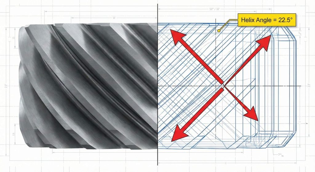
Can a helical gear cutting formula optimize Sunderland double helical gears?
Sunderland double helical gears represent a specialized application of the radial system where the helix angle is traditionally fixed at exactly 22.5 degrees. These herringbone structures eliminate axial thrust while providing the smooth engagement benefits typically associated with standard helical tooth profiles. You might be wondering. Applying a Sunderland helical gear cutting formula involves unique adjustments for the whole depth plus addendum to accommodate the specific internal gear manufacturing process.
Sunderland Design Features
Ready for the good part?
- Radial pressure angles stay at 20 degrees.
- Helix angles remain constant at 22.5 degrees.
- Opposite hands cancel out lateral forces.
- Tooth profiles undergo specific whole depth mods.
Key Takeaway: The Sunderland system provides a standardized method for producing balanced herringbone gears that support massive shock loads in mining equipment.
| Gear Feature | Value/Standard | Industrial Benefit |
|---|---|---|
| Whole Depth | 2.188m | Enhanced tooth root strength |
| Helix Angle | 22.5° | Zero net axial thrust |
| Machine Type | Sunderland | Specialized generating process |
Industrial kilns plus heavy-duty ball mills rely on these specific calculations to ensure long-term stability under continuous operational stress in harsh environments.
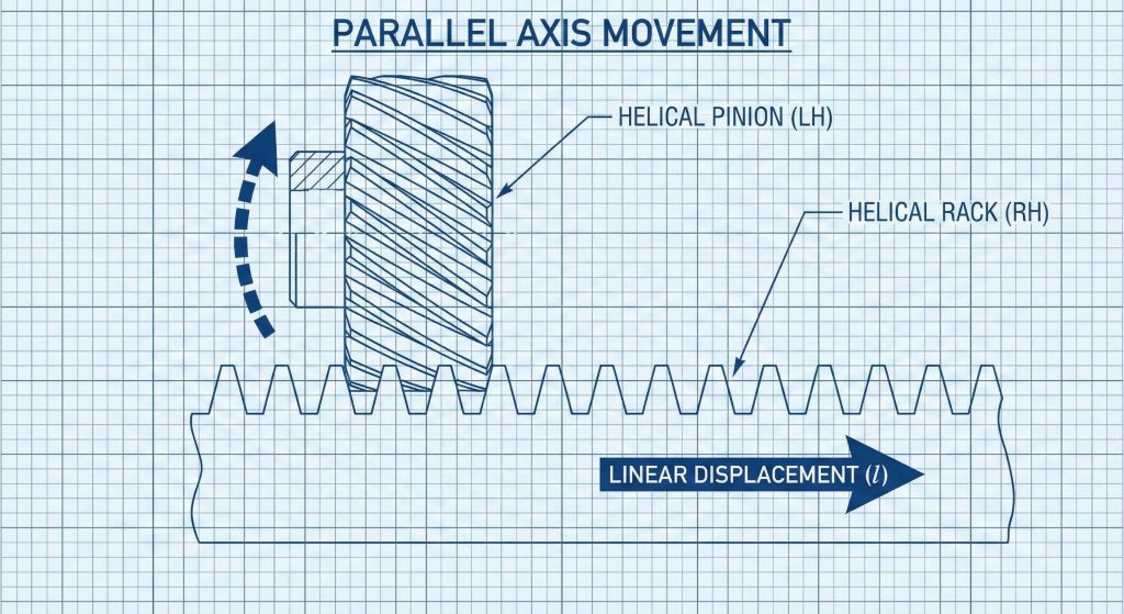
What helical gear cutting formula works best for helical racks?
Meshing a helical gear with a gear rack requires that both components share identical normal modules plus opposite helix hands for smooth linear motion. The linear displacement of the rack for one full revolution of the gear equals the product of the radial pitch plus the tooth count. What is the real story? Choosing an appropriate helical gear cutting formula allows designers to modify the helix angle until the displacement becomes a convenient integer value.
Helical Rack Mesh Alignment
But here is the kicker.
- Normal modules must match perfectly.
- Opposite hands enable parallel axis operation.
- Radial pitch determines the linear travel.
- Standard racks utilize zero profile shifts.
Key Takeaway: Proper rack-and-pinion synchronization depends on matching the transverse pitch to the desired linear travel per revolution of the drive shaft.
| Rack Component | Logic | Manufacturing Goal |
|---|---|---|
| Displacement | l = pi * m * z | Precise linear positioning |
| Handedness | Left/Right Pair | Proper tooth engagement |
| Tooth Angle | beta | Matches the mating gear |
Automated doors plus CNC laser systems utilize these precise linear calculations to maintain high positioning accuracy during rapid traversal across the machine bed.
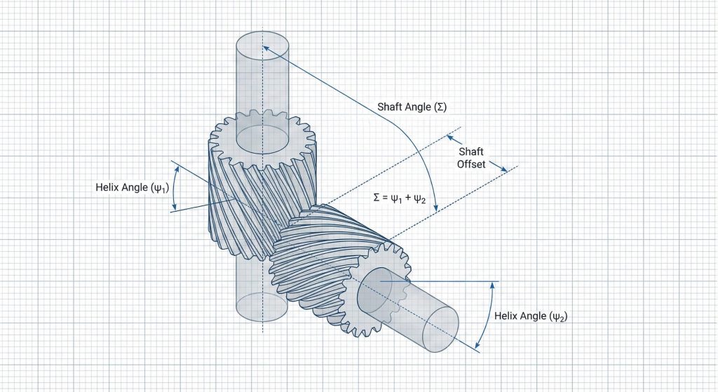
How does a helical gear cutting formula define crossed helical gear meshes?
Crossed helical gears connect skew shafts that usually reside at right angles but do not intersect within the gearbox assembly. Unlike parallel meshes the velocity ratio for crossed gears depends entirely on the tooth count rather than the ratio of the pitch diameters. This is where it gets interesting. Using a crossed helical gear cutting formula requires the normal modules to be identical even if the radial modules differ significantly.
Crossed Mesh Geometry
Ready for the good part?
- Shaft angles equal the sum of helixes.
- Velocity ratios use tooth counts only.
- Normal pressure angles must stay consistent.
- Point contact limits total load capacity.
Key Takeaway: Crossed helical gears offer extreme flexibility for interconnecting non-parallel shafts but they require careful lubrication due to sliding tooth contact.
| Configuration | Handedness | Shaft Relationship |
|---|---|---|
| Same Hand | Right/Right | Right angle shafts |
| Opposite Hand | Right/Left | Parallel axis shafts |
| Skew Angle | beta1 + beta2 | Defines total shaft tilt |
Designers frequently utilize these meshes in small instrument drives where space constraints prevent the use of traditional worm gear sets or bevel arrangements.
Is there a helical gear cutting formula for adjusting screw gear center distance?
Adjusting the center distance for screw gears involves manipulating the helix angles of both the pinion plus the mating gear while maintaining the shaft angle. Profile shifting adds a layer of complexity because the working pitch cylinders must be calculated based on the modified tooth thicknesses plus shifts. You might be wondering. A robust helical gear cutting formula allows for minor adjustments that accommodate existing housing dimensions without requiring a complete redesign of the transmission.
Screw Gear Distance Logic
What is the real story?
- Center distances utilize radial pitch diameters.
- Helix modifications must remain consistent overall.
- Profile shifts alter the effective mesh.
- Standard gears simplify the basic equation.
Key Takeaway: Manipulating helix angles provides a convenient way to fit gears into pre-defined center distances without changing the fundamental gear ratio.
| Adjustment Type | Method | Resulting Impact |
|---|---|---|
| Helix Tweak | Angle Change | Shifts the center distance |
| Profile Shift | x1 + x2 | Changes tooth thickness |
| Module Change | Standard Step | Large jump in distance |
Engineers must verify that these adjustments do not lead to excessive sliding friction which could compromise the efficiency of the B2B power transmission unit.
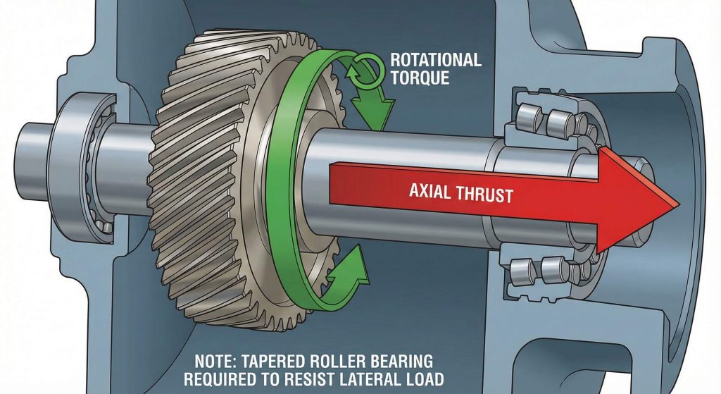
Does every helical gear cutting formula account for axial thrust loads?
Helical gears naturally generate axial thrust which acts as a lateral force on the bearings plus the housing during high-torque operation. The magnitude of this thrust depends directly on the helix angle plus the total transmitted load moving through the gear teeth. But here is the kicker. Applying a thrust-inclusive helical gear cutting formula helps engineers select appropriate tapered roller bearings that can withstand these significant parasitic forces over time.
Thrust Calculation Variables
Ready for the good part?
- Tangential loads drive the thrust force.
- Helix angles determine the axial multiplier.
- Opposite rotations change the thrust direction.
- Double helical designs cancel these forces.
Key Takeaway: Managing axial thrust is essential for bearing longevity especially when the helix angle exceeds twenty degrees in heavy industrial applications.
| Loading Factor | Impact | Design Solution |
|---|---|---|
| Transmitted Load | Primary Force | Robust gear tooth sizing |
| Helix Angle | Thrust Ratio | Angle optimization |
| Bearing Type | Load Support | Tapered or thrust bearings |
Failure to account for these lateral loads results in premature bearing wear plus shaft misalignment which eventually destroys the precision of the entire gear train.
How do bevel gear proportions differ from a helical gear cutting formula?
Bevel gears operate on a spherical basis where the tooth elements converge at a single apex to transmit power between intersecting shafts. Unlike a standard helical gear cutting formula which assumes cylindrical pitch surfaces bevel geometry relies on pitch cones with specific cone angles. This is where it gets interesting. Proportions for bevel gear teeth are referenced at the heel or the outer end because the dimensions vanish toward the center.
Bevel Gear Geometry Basics
What is the real story?
- Pitch diameters belong to cone frusta.
- Pressure angles typically stay at 20 degrees.
- Velocity ratios derive from cone angles.
- Octoid forms represent the modern standard.
Key Takeaway: Bevel gears require precise alignment of the pitch apex to ensure that the teeth roll together without sliding or binding during use.
| Geometry Element | Definition | Engineering Role |
|---|---|---|
| Pitch Apex | Convergence Point | Alignment reference |
| Heel | Large Tooth End | Dimensioning reference |
| Crown Gear | Basis Rack | Generation tool geometry |
Straight bevel gears remain the most common choice for right-angle drives when speeds remain below three hundred meters per minute in low-noise environments.
Which helical gear cutting formula ensures precision in Gleason straight bevels?
The Gleason system for straight bevel gears utilizes profile shifting to distribute strength evenly between the pinion plus the gear. This system ensures that the top clearance remains parallel along the entire tooth length which prevents interference at the toe or heel. You might be wondering. Using a Gleason-specific helical gear cutting formula prevents undercut in pinions with a small number of teeth by applying a positive profile shift.
Gleason System Advantages
Ready for the good part?
- Positive shifts strengthen small pinions.
- Parallel clearances ensure smooth meshing.
- Minimum tooth counts prevent damaging undercut.
- Miter gears require zero profile shifts.
Key Takeaway: The Gleason system is the industry standard for producing high-strength bevel gears that tolerate minor assembly misalignments without concentrating stress.
| Gear Set Type | Pinion Shift | Gear Shift |
|---|---|---|
| Speed Reducer | Positive | Negative |
| Miter Gear | Zero | Zero |
| Coniflex | Crowned | Crowned |
These calculations are vital for automotive differentials plus agricultural machinery where reliability under heavy loads is a non-negotiable requirement for procurement managers.
When should you use a helical gear cutting formula for spiral bevel designs?
Spiral bevel gears feature curved oblique teeth that engage gradually to provide quieter operation plus higher load capacity than straight versions. A specialized helical gear cutting formula for spiral teeth accounts for the spiral angle at the tooth center plus the hand of the spiral. But here is the kicker. Matching the hands of the spiral gear set is mandatory because a left-hand pinion must always mesh with a right-hand gear.
Spiral Bevel Performance
What is the real story?
- Gradual engagement reduces mechanical noise.
- Overlapping teeth increase total load capacity.
- Curved profiles require circular face cutters.
- Zerol versions offer zero spiral angles.
Key Takeaway: Spiral bevel gears are the superior choice for high-speed power transmission where noise reduction plus torque density are the primary design goals.
| Feature | Spiral Bevel | Zerol Bevel |
|---|---|---|
| Spiral Angle | Beta > 0 | Beta = 0 |
| Noise Level | Extremely Low | Moderate |
| Axial Thrust | Significant | Very Low |
Modern aerospace plus high-end industrial gearboxes utilize these complex spiral designs to achieve the highest possible efficiency within restricted weight plus volume envelopes.
Conclusion
Summary of technical gear technology highlights the necessity of precise mathematical modeling for helical plus bevel systems. Mastering the application of profile shifts plus system transformations ensures that industrial components perform reliably under extreme conditions. For professional assistance with your custom gear requirements or to discuss your drawings with our technical team contact us today.
Frequently Asked Questions
Q1: Can I use the same formula for normal plus radial helical gears?
No you must apply specific trigonometric conversions to account for the helix angle when moving between normal plus radial planes.
Q2: What’s the best way to eliminate axial thrust in a helical system?
The best solution is using a double helical or herringbone gear design which uses opposite tooth hands to cancel out lateral forces.
Q3: How do I calculate the velocity ratio for crossed helical gears?
You must use the tooth count ratio of the two gears because pitch diameter ratios are unreliable for non-parallel skew shaft meshes.
Q4: Why should I choose Gleason straight bevel gears over standard types?
Gleason gears offer superior tooth strength plus parallel top clearance which provides better load distribution plus assembly tolerance than standard bevel designs.
Q5: Is it possible to adjust the center distance of existing screw gears?
Yes you can modify the helix angles of both gears consistently to fit a specific center distance while maintaining the desired shaft angle.