
Single-envelope worm gears are notorious for a specific, costly failure mode: if the contact pattern isn’t perfectly aligned, friction skyrockets, leading to rapid bronze wear and premature system seizure. This type of gearing relies on a delicate line of contact between the steel worm and the bronze wheel, and even microscopic deviations in manufacturing can disrupt this balance. For equipment manufacturers, this isn’t just a maintenance issue; a gear failure in a remote mining conveyor or a high-speed packaging line means expensive downtime, emergency air-freight costs for replacements, and a damaged reputation with your customers. Here is the brutal truth: Standard “off-the-shelf” gears often lack the precise throat geometry required for long-term reliability, resulting in immediate overheating that strips teeth before the break-in cycle ends. Manufacturing these gears requires a strict protocol—specifically, matching the hob’s radius exactly to the worm shaft to ensure a perfect line of contact. At Yantong Tech, we don’t just cut gears; we engineer reliability by combining ISO-grade hobbing precision with full material traceability to deliver components that fit right the first time.
1. Hobbing Methods for Cutting a Worm Gear
How Does Tangential Feed Work?
Tangential feeding is the gold standard for high-precision worm gears, where the tapered hob enters from the side rather than plunging directly in. This method generates a more accurate involute profile because the cutting load is distributed gradually across more teeth. You might be wondering: Is this slower method worth it? Absolutely, as it creates the superior surface finish required for ISO Grade 6 applications.
When Is Radial Plunging Used?
Radial feed involves moving the hob directly into the gear blank until the correct center distance is reached. It is significantly faster than tangential hobbing but tends to leave a slightly rougher finish and a less precise contact pattern. This method is often the default for commercial-grade gears where cost and speed take precedence over ultimate precision.
Which Tooling Is Best for Cutting?
Selecting the right hob material is critical; carbide hobs are preferred for abrasive bronze alloys, while High-Speed Steel (HSS) is often sufficient for softer materials. Here is the deal: The hob’s radius must match the mating worm shaft exactly, or the contact pattern will be compromised. Using a generic hob size will result in point contact rather than the desired line contact.
Key Takeaway: The hob quality and feed method dictate the profile accuracy; tangential feed is non-negotiable for precision power transmission.
- Tangential Feed: Essential for high-load applications where surface finish and contact area are critical.
- Radial Feed: Best suited for high-volume, cost-sensitive production runs where minor faceting is acceptable.
- Tooling Accuracy: The hob must be a “Class A” tool to maintain the involute profile across thousands of cycles.
- Re-sharpening: Frequent hob sharpening is required to prevent geometric drift and thermal buildup.
Table 1: Radial vs. Tangential Feed Comparison
| Feature | Radial Feed (Plunging) | Tangential Feed |
|---|---|---|
| Mechanism | Hob moves straight into the blank center. | Hob feeds across the gear face axially. |
| Tool Type | Cylindrical Hob. | Tapered entry Hob. |
| Cycle Time | Fast (High production rate). | Slower (Precision focused). |
| Accuracy | ISO Grade 8-9 (Standard). | ISO Grade 5-7 (High Precision). |
| Setup Cost | Lower (Standard arbors). | Higher (Requires differential gearing). |
Expert Analysis:
At Yantong Tech, we utilize tangential feed hobbing for all OEM export orders to ensure the contact pattern is perfectly centered. We employ strict re-sharpening protocols to keep our hobs in Class A condition, ensuring the 1,000th gear has the same geometry as the first. This consistency is why clients like Mark in Germany trust us with their critical transmission components; they know our batch-to-batch deviation is virtually non-existent. We do not compromise on the cycle time if it means sacrificing the contact area that ensures the gear’s longevity.
2. Fly Cutting a Worm Gear for Prototypes
How To Setup the Fly Cutter?
Setting up a fly cutter involves grinding a single-point tool to the exact profile of the worm thread space. This tool is then mounted in a specialized arbor and synchronized with the rotating gear blank. But here’s the kicker: The setup requires extreme patience, as the tool must be perfectly centered to avoid cutting a “leaning” tooth profile.
Why Choose Fly Cutting Over Hobbing?
Fly cutting is the most cost-effective method when you only need to produce a few gears for prototyping or repair. It eliminates the need to purchase a custom hob, which can cost thousands of dollars and take weeks to manufacture. This flexibility allows engineers to test different ratios or profiles without a massive upfront investment.
What Are the Limitations of Fly Cutting?
The primary limitation is the extremely slow cycle time, as a single cutting edge must remove all the material. Additionally, tool wear is accelerated, which can lead to slight profile variations from the first tooth to the last if not monitored. It is not suitable for mass production where consistency and speed are paramount.
Key Takeaway: Fly cutting is your secret weapon for cost-effective prototyping and emergency maintenance replacements, but it cannot replace hobbing for volume.
- Cost Efficiency: Removes the barrier of entry for custom gear ratios by utilizing standard tool bits.
- Flexibility: Allows for immediate adjustment of tooth thickness and profile without waiting for new tooling.
- Cycle Time: Extremely slow, often taking 10-20 times longer than hobbing a similar part.
- Skill Requirement: Demands a master machinist to grind the tool bit and verify the center height.
Table 2: Fly Cutting vs. Hobbing Decision Matrix
| Criteria | Fly Cutting | Tangential Hobbing |
|---|---|---|
| Quantity | 1 – 5 pieces (Prototyping/Repair) | > 50 pieces (Production) |
| Tooling Cost | Negligible ($50 – $100) | High ($1,500 – $5,000+) |
| Lead Time | Immediate (Hours) | Long (4-6 weeks for hob) |
| Consistency | Operator Dependent | Machine Dependent |
| Surface Finish | Excellent (if feed is slow) | Consistent/Uniform |
Expert Analysis:
While fly cutting is excellent for validating a design, we caution our clients against using it for pilot runs intended for endurance testing. The surface structure generated by a single-point tool differs slightly from the multi-tooth generation of a hob, which can affect oil retention during the initial break-in. Yantong Tech recommends fly cutting solely for dimensional fit checks or emergency replacement parts where lead time is the only priority. For any application requiring load testing, we advise investing in a specific hob to guarantee the results match mass production reality.
3. Gashing Steps Before Cutting a Worm Gear
Why Is Roughing So Important?
Gashing removes the bulk of the material—often up to 90%—before the final finishing cut takes place. Attempting to cut a worm gear in a single pass puts massive stress on the tool and workpiece, leading to thermal expansion and poor pitch accuracy. Ready for the good part? Gashing allows the expensive finishing hob to cut cool and precise, significantly extending its service life.
How To Ensure Accurate Indexing?
Accurate indexing during the gashing phase is non-negotiable to ensuring the teeth are spaced correctly. Whether using a mechanical dividing head or a CNC rotary table, the cutter must be perfectly aligned with the blank’s axis. Modern CNC gashing eliminates human indexing errors, ensuring the spacing between every tooth is identical within microns.
How Much Allowance for Finishing?
Leaving the correct amount of stock for the finishing pass is a delicate balance. Too much stock causes the finishing tool to deflect, while too little can leave witness marks from the roughing cut. Typically, a stock allowance of 0.2mm to 0.5mm per flank is ideal for achieving the final profile without stressing the tool.
Key Takeaway: Never skip gashing on modules larger than 2.0; it safeguards your final dimensional accuracy and protects your finishing tools.
- Thermal Control: Removes heat with the chips, keeping the blank at ambient temperature for the final pass.
- Tool Life: Protects expensive Class A hobs from the heavy wear of roughing cuts.
- Pitch Accuracy: Reduces the cutting forces that cause machine deflection and indexing errors.
- Process Stability: Creates a predictable environment for the finishing operation.
Table 3: Recommended Stock Allowance by Module
| Module Range | Recommended Stock Allowance (per flank) |
|---|---|
| Module 1 – 2 | 0.10mm – 0.15mm |
| Module 2 – 4 | 0.15mm – 0.25mm |
| Module 4 – 6 | 0.25mm – 0.35mm |
| Module 6 – 8 | 0.35mm – 0.50mm |
| Module > 8 | 0.50mm – 0.75mm |
Expert Analysis:
We implement a rigorous two-stage cutting process at Yantong Tech to minimize thermal distortion. By removing the majority of material during gashing and allowing the part to thermally stabilize—sometimes even removing it from the machine to cool—we ensure the final pass is incredibly precise. This attention to detail is crucial for maintaining the tight tolerances required by our US partners like Michael, who demand “no surprises” during assembly.
4. CNC Milling for Cutting a Worm Gear
Can 5-Axis Mills Cut Worm Gears?
Yes, modern 5-axis CNC mills are fully capable of generating complex worm gear profiles using standard end mills. This method interpolates the gear shape through software rather than relying on the physical geometry of a cutter. This is where it gets interesting: It allows for the creation of completely custom profiles that would be impossible to hob without custom tooling.
What Software Generates the Profile?
Advanced CAD/CAM software is required to generate the parametric toolpaths needed for 5-axis milling. The software calculates the precise movement of the tool to simulate the meshing action of the worm. Without this sophisticated programming, achieving the correct conjugate action between the worm and wheel is virtually impossible.
How To Control Precision in Milling?
Precision in milling is controlled by managing tool deflection and thermal expansion during the cut. High-quality carbide end mills and rigid machine setups are essential to prevent the tool from pushing away from the work. Frequent in-process probing can verify that the dimensions are staying within tolerance throughout the long cycle.
Key Takeaway: CNC milling offers unmatched flexibility for complex geometry verification without the need for custom, lead-time-heavy tooling.
- No Custom Hobs: Uses off-the-shelf end mills to generate any gear module or pressure angle.
- Geometry Verification: Ideal for testing modified tooth profiles before committing to hard tooling.
- Complexity: Requires high-end CAM software and skilled programmers to generate valid toolpaths.
- Cost Factor: High machine hourly rates make this method expensive for anything beyond prototyping.
Table 4: CNC Milling vs. Traditional Hobbing
| Feature | CNC 5-Axis Milling | Traditional Hobbing |
|---|---|---|
| Profile Generation | Software Interpolation | Tool Geometry |
| Setup Time | High (Programming intensive) | Medium (Mechanical setup) |
| Tooling Cost | Low (Standard End Mills) | High (Custom Hobs) |
| Throughput | Very Low | High |
| Application | R&D, Complex Geometry | Mass Production |
Expert Analysis:
Our approach involves using DMU 5-axis machines for complex geometry verification before we commit to mass production. This allows us to validate the contact pattern and tooth geometry digitally and physically, providing our clients with a functional prototype that mirrors the final product. It’s part of our commitment to being a reliable industrial partner who solves problems before they reach the production line.
5. Material Effects on Cutting a Worm Gear
How To Machine Centrifugal Bronze?
Centrifugally cast bronze, such as CuSn12, produces short, brittle chips but is prone to grabbing the tool if the geometry isn’t correct. Here is the brutal truth: Using standard geometries designed for steel will result in poor surface finishes and rapid tool wear. Sharp, positive rake angles and abundant coolant are required to flush chips and prevent heat buildup.
Is Cutting Hardened Steel Possible?
Cutting hardened steel worms requires specialized processes like skiving or hard-hobbing after heat treatment. These techniques use carbide tools to machine the hardened surface, eliminating distortion caused by the furnace. It ensures the final geometry is perfect, but it demands rigid machinery and expensive tooling.
How To Manage Thermal Expansion?
Bronze has a high coefficient of thermal expansion, meaning it grows significantly when it gets hot. If the gear is cut while hot, it will be undersized once it cools to room temperature. Flood coolant and strict temperature control in the machining area are vital to maintaining pitch accuracy.
Key Takeaway: Material stability directly affects pitch accuracy; you must control the temperature to control the dimension.
- Chip Evacuation: Critical in bronze to prevent re-cutting chips which ruins surface finish.
- Coolant Strategy: High-pressure oil is preferred to lubricate the cut and carry away heat.
- Tool Geometry: Positive rake angles help “slice” bronze rather than “pushing” it, reducing heat.
- Distortion: Internal stresses in cast blanks can release during cutting; stress-relieving cycles are mandatory.
Table 5: Machinability & Coolant Strategies
| Material | Machinability Rating | Coolant Strategy | Chip Characteristics |
|---|---|---|---|
| Phosphor Bronze (CuSn12) | Good (Short Chips) | Flood Oil/Emulsion | Brittle, abrasive dust. |
| Aluminum Bronze | Difficult (Gummy) | High Pressure Flood | Long, stringy, tough. |
| Cast Iron | Excellent | Dry / Air Blast | Powder / Short chips. |
| Hardened Steel (58HRC) | Poor (Hard) | Oil Mist / Dry | Hot, blue sparks. |
Expert Analysis:
At Yantong, we verify the chemical composition of every bronze batch before casting to ensuring the Tin (Sn) content matches the friction requirements. For our German clients, we provide material certificates (EN 10204 3.1) proving the material properties. We understand that consistent machinability leads to consistent gears, which is why we never compromise on raw material quality.
6. Inspection After Cutting a Worm Gear
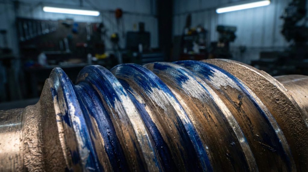
How To Check the Contact Pattern?
Verifying the contact pattern involves applying a thin layer of engineering blue (layout dye) to the worm and rotating it against the wheel. The resulting pattern shows exactly where the teeth are meshing. You might be wondering: What does a good pattern look like? It should be slightly offset towards the leaving side to allow an entry gap for lubricant.
How To Measure Tooth Thickness?
Tooth thickness is measured using gear verniers or the “over pins” method, where precision balls or pins are placed between the teeth. This measurement verifies that the backlash (clearance) will be correct when the gears are assembled. Accurate thickness is critical to preventing binding or excessive play in the final gearbox.
Why Analyze Runout and Lead Error?
Runout and lead error directly impact the smoothness of the transmission and the noise level. A wobbling gear (runout) creates vibration, while lead error concentrates the load on the edges of the teeth. Advanced inspection equipment is needed to detect these micron-level deviations that can drastically shorten gear life.
Key Takeaway: The contact pattern is the ultimate truth-teller; it validates the entire machine setup and tool alignment.
- Blueing Test: The primary method for verifying the conjugate action between worm and wheel.
- Composite Error: Checks the total radial variation during rotation, indicating runout.
- Backlash Verification: Ensures there is enough room for the oil film but not enough for shock loading.
- Documentation: Real quality control relies on recorded data points, not just visual checks.
Table 6: ISO 1328 Tolerance Classes
| ISO Class | Application | Manufacturing Method | Yantong Standard |
|---|---|---|---|
| Class 5-6 | Precision Indexing | Tangential Hobbing | Premium |
| Class 7-8 | General Conveyors | Standard Hobbing | Standard |
| Class 9-10 | Manual Drives | Radial Plunging | Economy |
| Class 11-12 | Non-Critical | Casting/Molding | N/A |
Expert Analysis:
We integrate detailed CMM reports and lead profile charts into our quality assurance process to prove quality to German and US engineers. Traceability is key; we provide material heat numbers and heat treatment curves linked to specific gear batches. This level of transparency builds trust, ensuring Michael in the USA knows exactly what he is putting into his machines.
7. Common Issues When Cutting a Worm Gear
How To Prevent Tool Chatter?
Tool chatter creates a distinct wavy pattern on the gear flanks, destroying the surface finish and increasing noise. It is often caused by a lack of rigidity in the setup or dull cutting tools. But here’s the kicker: Simply slowing down the feed rate often fixes the issue, as does ensuring the workpiece is clamped as close to the cut as possible.
Why Does the Center Distance Matter?
The center distance between the worm and the wheel is the most critical dimension in the entire assembly. If this distance is incorrect during cutting, the contact pattern will shift, reducing the load-bearing area. Manufacturers must cut the gear at the exact center distance specified in the design to ensure proper meshing.
How To Avoid Workpiece Distortion?
Thin-walled gear blanks are prone to distortion from the clamping forces and cutting pressure. Using custom soft jaws or expanding mandrels can distribute the clamping force evenly. Additionally, stress-relieving the blanks before the final finishing cut helps maintain roundness and dimensional stability.
Key Takeaway: Process stability is paramount; rigid setups and sharp tools prevent the vibrations that ruin gear surfaces.
- Rigidity: Use tailstocks and steady rests for long shafts to dampen vibration.
- Tool Maintenance: A dull hob increases cutting pressure, leading to deflection and chatter.
- Fixture Design: Proper clamping prevents the part from “springing” out of shape after removal.
- Parameter Optimization: Balancing speed and feed is essential to avoid resonance frequencies.
Expert Analysis:
Chatter and distortion are often symptoms of rushing the process. At Yantong Tech, we prioritize process stability over raw speed. We design custom fixtures for thin-walled gears to ensure the clamping pressure is uniform. By conducting a “first article inspection” including a Blueing Test on every setup, we catch these issues before running the full batch, saving our clients from the headache of receiving a crate of noisy gears.
Conclusion
Manufacturing single-envelope worm gears is a balancing act between geometry, material science, and cutting dynamics. The difference between a gear that lasts five years and one that fails in five weeks often comes down to the “invisible” details: the precision of the tangential feed, the accuracy of the contact pattern, and the purity of the bronze alloy. Choosing the right method—whether it’s hobbing for volume or fly cutting for prototypes—is the first step toward reliability.
At Yantong Tech, we combine advanced CNC hobbing with rigorous CMM inspection to ensure that every gear we produce meets the highest standards of reliability. We don’t just sell gears; we offer the peace of mind that comes from knowing your transmission components are engineered to ISO standards and backed by full traceability. Our sales team are engineers who understand “Contact Patterns” and “Backlash,” not just price lists, ensuring we speak your language.
Ready to secure your supply chain? Contact our engineering team today to review your gear prints and discover how a reliable industrial partner can transform your production quality. Let’s build trust through transparent manufacturing data.
FAQs
Q1: Can I cut a worm gear on a standard universal milling machine?
Answer: Yes, but it is risky and slow. It requires a dividing head and perfect synchronization between the table feed and index head (or a specific gearing setup). While acceptable for emergency repairs, the risk of operator error is high, and achieving a perfect involute profile is difficult compared to dedicated hobbing.
Q2: What is the best method for high-volume worm gear manufacturing?
Answer: Hobbing with a tangential feed is the superior choice. This method provides the most consistent tooth geometry and fastest cycle times relative to quality. While radial plunging is faster, tangential hobbing ensures the high precision (ISO 6-7) required for modern, quiet-running gearboxes.
Q3: Can I use a standard involute cutter for worm gears?
Answer: No, you absolutely shouldn’t. Worm gears have a specific throat radius that matches the curvature of the worm shaft. Standard involute cutters create a straight tooth profile that results in “point contact” rather than “line contact,” leading to extreme stress concentrations and rapid failure.
Q4: What is the critical tolerance when cutting a worm gear?
Answer: The center distance and lead angle are critical. If the center distance doesn’t match the housing exactly, the pitch line shifts, causing poor meshing. Even worse, if the lead angle deviates, the gear set will suffer from edge loading, which wipes away lubricant and causes immediate scoring.
Q5: Why is bronze the standard material for worm wheels?
Answer: Bronze is used because of its low coefficient of friction and “sacrificial” nature. When paired with a hardened steel worm, the softer bronze creates a low-friction interface and will conform slightly to the harder steel worm during the break-in period, improving the contact patch without damaging the expensive worm shaft.