
Technical data for helical gears consists of the specific geometric and mechanical parameters—such as helix angle, module (normal and transverse), pressure angle, and face width—that dictate the gear’s torque capacity, axial thrust, and noise-damping characteristics.
The challenge most engineers face is the constant battle against gear noise, vibration, and premature tooth wear. These issues are often the result of miscalculated helix angles or mismatched module systems that lead to poor mesh alignment.
Every hour of downtime caused by a failed transmission system costs thousands in lost productivity and emergency repairs. Without the right technical foundation, even a minor deviation in gear data can lead to catastrophic bearing failure due to unmanaged axial thrust. Precise helical gear data provides the solution, allowing for the design of quiet, high-load systems that operate with maximum efficiency and longevity.
What are the primary features of helical gear data?
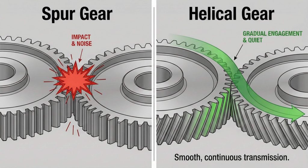
When analyzing helical gear data, the primary features focus on the gear’s ability to provide smooth, high-speed power transmission. Unlike spur gears, helical teeth engage gradually, which significantly reduces impact noise and vibration. This makes them the preferred choice for industrial speed reducers and machine tools.
Why does gradual engagement matter?
Think about this:
- Noise Reduction: The overlapping tooth engagement dampens the “clatter” typical of straight-cut gears.
- Higher Load Capacity: Because more teeth are in contact at any given time, the load is distributed over a larger surface area.
- Compact Design: Helical gears can often transmit higher torque than spur gears of the same size.
Key Takeaway: Helical gears are engineered for high-performance environments where noise suppression and high torque density are non-negotiable.
Technical Summary: Spur vs. Helical Parameters
| Parameter | Spur Gear | Helical Gear |
|---|---|---|
| Tooth Engagement | Instantaneous | Gradual / Sequential |
| Noise Level | Moderate to High | Low to Minimum |
| Axial Thrust | None | Significant (Directional) |
| Contact Ratio | Lower | Higher |
How do transverse and normal modules affect helical gear data?
Interpreting helical gear data requires a clear understanding of the two different module systems: the normal module and the transverse module. Because the teeth are cut at an angle, the “pitch” of the gear depends on which direction you measure from. Following a master helical gear design procedure is essential to ensure these two systems are never confused during manufacturing.
Normal vs. Transverse: Which one do you use?
Here is the deal:
- Normal Module ($m_n$): This is measured perpendicular to the tooth. Standard cutters are typically based on this module.
- Transverse Module ($m_t$): This is measured in the plane of rotation (the face of the gear). It is used to calculate the pitch diameter.
- Interchangeability: Gears of different module systems will not mesh, even if the “size” looks similar.
Key Takeaway: Always specify whether your data refers to the normal or transverse system to avoid catastrophic mismatching during assembly.
Technical Summary: Module System Comparison
| System | Measurement Plane | Primary Use |
|---|---|---|
| Normal Module | Perpendicular to helix | Tool selection and tooth strength |
| Transverse Module | Plane of rotation | Calculating Pitch Diameter ($d = z \cdot m_t$) |
Why is the helix angle critical for helical gear data calculations?
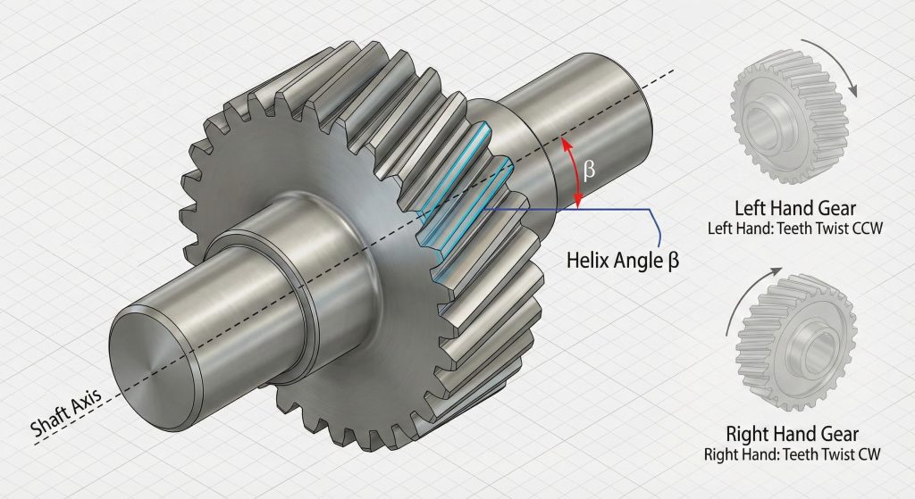
Calculating helical gear data accurately is impossible without defining the helix angle ($\beta$). This angle determines how much the teeth “twist” around the gear cylinder. It is the defining characteristic that separates helical gears from spur gears and dictates the resulting axial thrust.
Understanding the angle dynamics
Check this out:
- Angle Range: Most industrial gears use a helix angle between 15° and 30°.
- Directionality: You must specify Right Hand (R) or Left Hand (L). For parallel shafts, you need one of each to mesh.
- Impact on Diameter: As the helix angle increases, the pitch diameter also increases for the same number of teeth.
For specific calculation steps, you can learn how to calculate accurate helix angle dimensions to ensure your housing fits the resulting gear size.
Key Takeaway: The helix angle is the “engine” of the gear’s performance; higher angles provide smoother motion but generate more side-loading (thrust).
Technical Summary: Helix Angle Impact
| Helix Angle ($\beta$) | Noise Level | Axial Thrust | Manufacturing Complexity |
|---|---|---|---|
| 0° (Spur) | High | Zero | Low |
| 15° | Low | Moderate | Medium |
| 45° | Minimum | Very High | High |
How is the pressure angle defined in helical gear data?
Defining helical gear data involves identifying two different pressure angles: the normal pressure angle ($\alpha_n$) and the transverse pressure angle ($\alpha_t$). The pressure angle dictates the direction of the force transmitted between the teeth and influences the gear’s resistance to undercutting.
The geometry of the mesh
Keep this in mind:
- Standard Values: Most helical gears utilize a 20° normal pressure angle.
- Transverse Calculation: The transverse pressure angle is always larger than the normal pressure angle due to the helix.
- Force Distribution: A correct pressure angle ensures that the line of action stays within the tooth profile, preventing premature wear.
Key Takeaway: Matching the pressure angle of mating gears is non-negotiable for achieving a theoretically correct involute mesh.
Technical Summary: Pressure Angle Relationships
| Angle Type | Symbol | Relationship to Helix ($\beta$) |
|---|---|---|
| Normal Pressure Angle | $\alpha_n$ | Measured perpendicular to the tooth |
| Transverse Pressure Angle | $\alpha_t$ | $\tan \alpha_t = \tan \alpha_n / \cos \beta$ |
How is axial thrust managed in helical gear data sets?
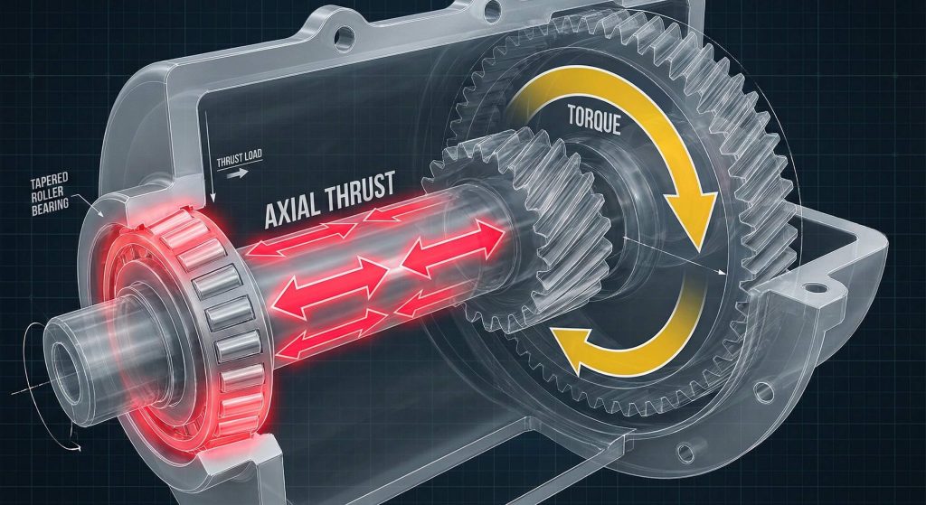
Understanding helical gear data requires addressing the inevitable byproduct of the helix: axial thrust. Because the teeth are at an angle, the force of the mesh pushes the gear along the shaft. If you want to boost industrial efficiency, your assembly must be designed to withstand these lateral forces.
Managing the push
The bottom line is:
- Bearing Selection: Deep-groove ball bearings or tapered roller bearings are usually required to handle the thrust.
- Direction of Force: Thrust direction changes based on the helix hand (R/L) and the direction of rotation (CW/CCW).
- Thrust Washers: In low-load applications, hardened thrust washers may suffice, but high-torque units require robust bearing sets.
Key Takeaway: Axial thrust is not a “defect” but a fundamental property that must be accounted for in the gearbox housing and bearing specifications.
Technical Summary: Thrust Force Variables
| Variable | Increase Value | Effect on Axial Thrust |
|---|---|---|
| Torque | Up | Increases Proportionally |
| Helix Angle | Up | Increases Significantly |
| Pitch Diameter | Up | Decreases (for same torque) |
What role does pitch measurement play in helical gear data?
Measuring helical gear data for pitch is the only way to ensure the gears will actually fit together on their designated center distances. Just like the module, pitch is split into normal pitch ($p_n$) and transverse pitch ($p_t$). Mastering the helical gear cutting formula is the best way to verify these measurements during the machining process.
Precision in the pitch
You need to know:
- Pitch Diameter ($d$): This is the theoretical circle where the mesh occurs.
- Base Pitch: This is the distance between corresponding points on adjacent teeth along the line of action.
- Lead ($L$): This is the axial distance the gear tooth would travel if it completed one full revolution.
Key Takeaway: Pitch is the “language” gears use to communicate; any error in pitch measurement leads to “gear jump” and vibration.
Technical Summary: Pitch Types
| Pitch Type | Measurement Path | Calculation Basis |
|---|---|---|
| Normal Pitch | Perpendicular to teeth | $\pi \cdot m_n$ |
| Transverse Pitch | Circular arc on face | $\pi \cdot m_t$ |
| Axial Pitch | Parallel to shaft | $p_n / \sin \beta$ |
How does material selection impact helical gear data results?
Refining helical gear data often leads to a discussion about materials and heat treatment. The “allowable torque” listed in technical tables is entirely dependent on the material’s surface durability and bending strength. While S45C carbon steel is a standard, high-load applications often demand alloy steels with specialized hardening.
Choosing the right “skin”
Consider this:
- Hardness: Induction hardening the teeth increases wear resistance but can cause material distortion.
- Precision Grades: Heat treatment can drop the gear’s precision by 1 or 2 grades (e.g., from Grade 4 to Grade 6) due to thermal stress.
- Machinability: Some materials are easier to cut, which allows for tighter tolerances on the helix angle.
Key Takeaway: Your technical data is only as good as the material it’s written on; ensure your strength calculations match your heat treatment plan.
Technical Summary: Material Properties
| Material | Heat Treatment | Durability | Best For |
|---|---|---|---|
| S45C Carbon Steel | None / Normalized | Medium | General Industrial |
| SCM440 Alloy Steel | Hardened & Tempered | High | High-Torque Drives |
| MC Nylon | None | Low | Silent, Low-Load |
How do you measure tooth thickness for helical gear data?
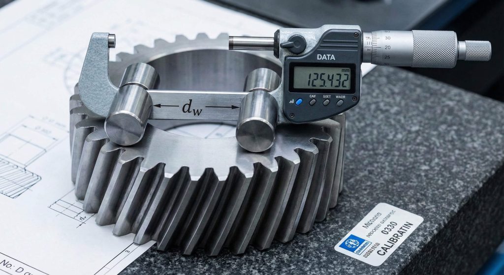
Verifying helical gear data involves precise measurement of tooth thickness. This is usually done using the “Span Measurement” method or by measuring “Over Pins.” Because helical teeth are curved, standard calipers used for spur gears may provide inaccurate readings if not applied at the correct angle.
Accuracy in the hand
The reality is:
- Span Measurement ($W$): This measures the distance across a certain number of teeth along the base cylinder.
- Over-Pin Diameter ($d_w$): Precision pins are placed in the tooth gaps, and the distance across them is measured.
- Backlash Correlation: Tooth thickness is the primary variable used to adjust the amount of backlash in a gear set.
Key Takeaway: Accurate thickness measurements are the final gatekeeper for quality control, ensuring the gear fits its housing without binding.
Technical Summary: Measurement Methods
| Method | Tool Required | Advantage |
|---|---|---|
| Span Measurement | Disc Micrometer | Fast, no pins needed |
| Over Pins (or Balls) | Standard Micrometer | Extremely accurate for profile |
| Chordal Thickness | Gear Tooth Caliper | Measures at the pitch line |
Why is backlash essential for helical gear data accuracy?
Optimizing helical gear data means finding the “Goldilocks” zone for backlash. Backlash is the clearance between mating teeth that prevents jamming. If there is too much, you get noise and positioning errors; if there is too little, the gears will overheat and seize.
Finding the clearance
Here is why it’s vital:
- Thermal Expansion: As gears work, they heat up and expand. Backlash provides the room for this growth.
- Lubrication Film: A small gap is necessary to allow oil to coat the tooth surfaces.
- Center Distance Tolerance: If your shaft centers are slightly off, adjustable backlash settings can compensate.
Key Takeaway: Zero backlash is rarely the goal; controlled, intentional backlash is the secret to a long-lasting gear life.
Technical Summary: Backlash Considerations
| Backlash Level | Noise | Heat Generation | Precision |
|---|---|---|---|
| Too Tight | Low (initially) | Very High | High |
| Standard | Moderate | Low | Medium |
| Too Loose | High | Low | Low |
How does lubrication maintain helical gear data integrity?
Preserving helical gear data performance over time is impossible without a robust lubrication strategy. Because helical gears have a sliding component to their mesh (unlike the pure rolling of spur gears), they generate more friction-related heat.
Keeping it cool
Follow these rules:
- Oil Bath: For standard speeds, a simple splash lubrication system works well.
- Forced Circulation: High-speed, high-load gearboxes require pumped oil to dissipate heat effectively.
- Viscosity: The oil must be thick enough to maintain a film under pressure, but thin enough to flow into the helix gaps.
If you are looking for precision helical gear products, always check the recommended lubrication methods to ensure warranty compliance.
Key Takeaway: Without proper lubrication, the most precisely calculated helical gear will fail due to surface pitting in a matter of hours.
Technical Summary: Lubrication Methods
| Method | Speed Range | Complexity | Cooling Ability |
|---|---|---|---|
| Grease | Low | Low | Low |
| Splash (Oil Bath) | Medium | Medium | Medium |
| Forced Oil | High | High | High |
Conclusion
At Gear Aide, we believe that precision engineering is the heartbeat of industrial progress. Our mission is to provide the technical clarity and high-performance components that allow engineers to push the boundaries of what’s possible in power transmission.
Ready to optimize your next project with precision helical gear data?
Quote Now to connect with our engineering team and secure the components you need for a smooth, reliable build.
FAQ
Q: Can a right-hand helical gear mesh with another right-hand helical gear?
A: On parallel shafts, no. You must use one Right Hand and one Left Hand gear. However, they can mesh at a 90-degree angle (as screw gears) if both are the same hand.
Q: Why are helical gears more expensive than spur gears?
A: The manufacturing process is more complex, requiring specialized hobbing machines that can coordinate the rotation of the gear blank with the axial movement of the cutter to create the helix.
Q: What is the most common helix angle for industrial gears?
A: Most standard industrial helical gears utilize a 15-degree to 20-degree helix angle to balance noise reduction with manageable axial thrust.
Q: How do I calculate the center distance for a helical gear set?
A: The formula is $a = (d_1 + d_2) / 2$, where the pitch diameters ($d$) are calculated using the transverse module.
Q: Does a helical gear have a higher efficiency than a spur gear?
A: Actually, they are slightly less efficient (about 1-2% less) due to the axial thrust and increased sliding friction, though the benefits in noise and load capacity usually outweigh this.