Introduction
When your industrial equipment suffers from excessive noise or premature wear, it is usually a sign of poor tooth engagement caused by inadequate design specifications. These failures can agitate your production schedule and inflate maintenance budgets significantly through unexpected downtime and costly replacement parts. Implementing rigorous helical gear calculations ensures every tooth interacts with precision, extending the service life of your transmission systems across diverse environments.
Why use helical gear calculations for normal systems?
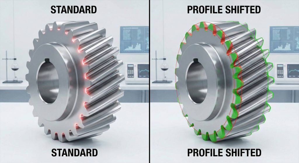
You use helical gear calculations in normal systems because they allow you to implement profile shifting to optimize tooth engagement and prevent undercutting in standard metric environments. This approach is essential because meshing in the axial direction mimics spur gear behavior while providing the benefits of a helical path. By adjusting the normal coefficient of profile shift, you can maintain standard geometries or customize them for specific heavy-load requirements.
How does profile shifting improve performance?
Let’s dive deeper. Profile shifting increases the strength of the tooth root and reduces the risk of interference during high-speed operation. This is particularly useful when you are working with small tooth counts that would otherwise suffer from manufacturing defects or mechanical weakness.
- Prevents tooth undercutting during the fabrication process.
- Optimizes the contact ratio for smoother power delivery.
- Allows for adjustments in center distance without changing modules.
Key Takeaway: Normal system calculations provide the versatility to shift profiles, ensuring that even compact gear sets remain durable under high stress.
| Parameter | Symbol | Purpose |
|---|---|---|
| Normal Module | $m_n$ | Standardizes tooth size across the normal plane |
| Working Pressure Angle | $\alpha_{wt}$ | Establishes the force direction in the axial system |
| Profile Shift Coefficient | $x_n$ | Adjusts tooth thickness to prevent undercutting |
How do helical gear calculations change in radial layouts?
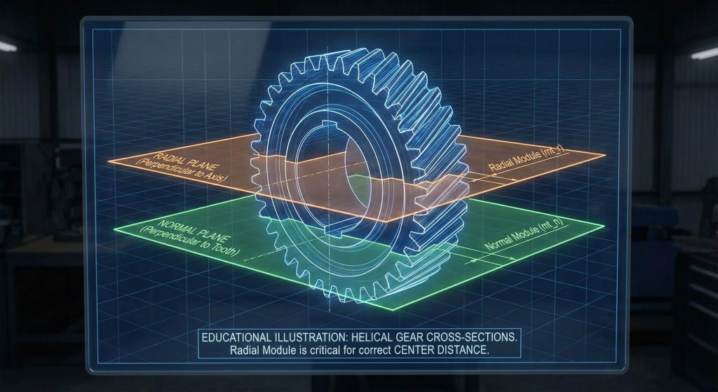
They change by focusing on the plane perpendicular to the gear axis, requiring specific mathematical transformations involving the cosine of the helix angle for accurate helical gear calculations. When performing these transformations, you must derive the radial module from the normal system to ensure a perfect fit within the housing. This system is critical for determining the exact center distance between mating parts and ensuring the physical assembly matches engineering drawings.
Transitioning from normal to radial systems
Here is the catch. You cannot simply use normal parameters in a radial setup without risking severe backlash issues or gear binding during assembly. Accurate transformations ensure that the tooth integrity remains intact across the entire width of the gear face, supporting higher torque capacity.
- Radial module depends on the cosine of the helix angle.
- Center distance accounts for both reference circle diameters.
- Radial pressure angles differ from normal pressure angles.
Key Takeaway: Radial calculations are the primary tool for verifying center distances and ensuring that the physical assembly matches your engineering drawings.
| Requirement | Calculation Focus | Typical Result |
|---|---|---|
| Radial Module | Perpendicular plane | Precise center distance fit |
| Standard Gear Check | $x_{t1} = x_{t2} = 0$ | No profile shift required |
| Inverse Equations | Reference circles | Validation of center distance |
When are helical gear calculations used for double sets?
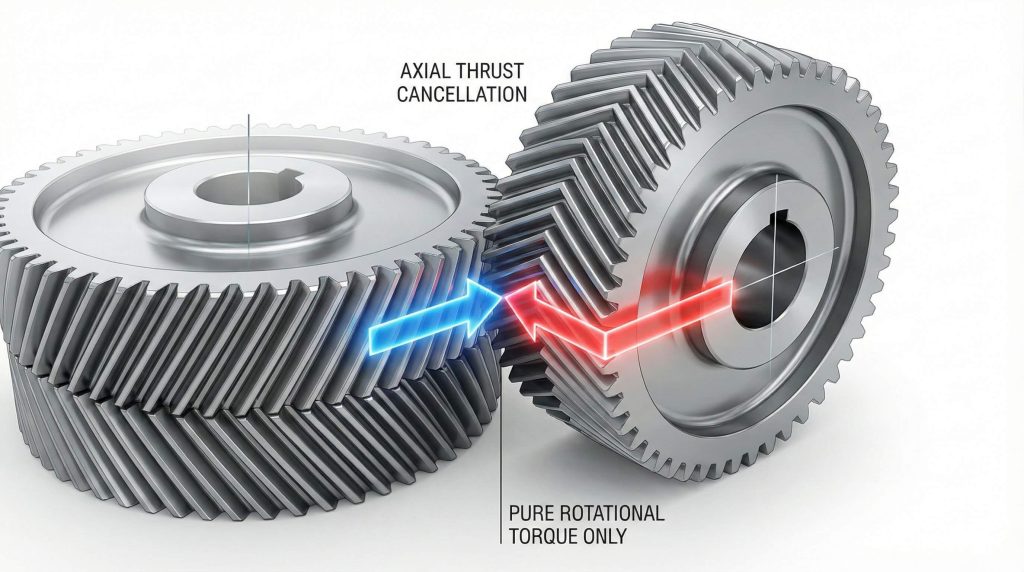
You use helical gear calculations for double sets when designing herringbone gears to neutralize axial thrust while maintaining high torque capacity for heavy machinery. Specialized designs like the Sunderland tooth profile require you to utilize specific radial pressure angles, typically set at 20 degrees to maximize efficiency. These designs are unique because they use the radial system to define the addendum and whole depth variations, preventing the gear from moving laterally under load.
Managing thrust in heavy-duty applications
Think about this. By using two opposing helix angles on the same gear, you essentially cancel out the axial force that often wears down expensive bearings. This makes double helical gears the gold standard for mining and heavy manufacturing equipment where reliability is paramount.
- Neutralizes internal axial thrust forces during operation.
- Increases tooth overlap for exceptionally quiet operation.
- Supports significantly higher shock loads than single helical types.
Key Takeaway: Double helical designs represent the peak of efficiency for high-torque systems where bearing longevity is a top priority.
| Feature | Sunderland Profile | Standard Helical |
|---|---|---|
| Helix Angle | Usually 22.5° | Variable |
| Pressure Angle | 20° Radial | Variable Normal |
| Whole Depth | Specified by module | Variable by profile shift |
Do helical gear calculations optimize rack systems?
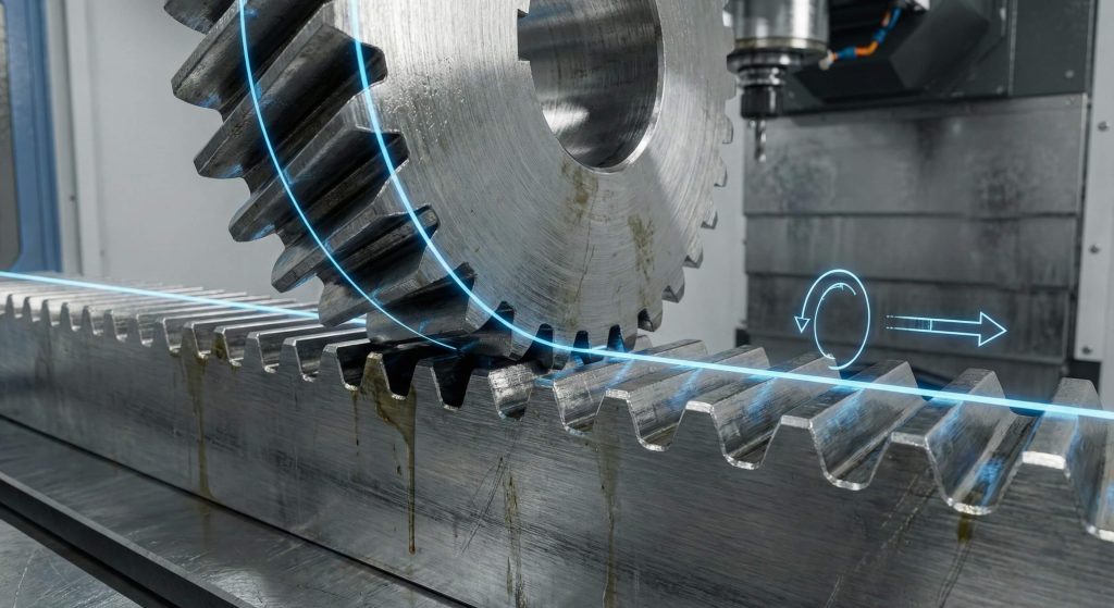
Yes, helical gear calculations define the linear displacement per gear rotation and ensure the rack and pinion share the same helix angle with opposite hands. These calculations are essential for converting rotational torque into smooth, continuous linear motion in CNC machines and automated industrial doors. You must calculate the displacement as the product of the radial pitch and the number of teeth on the mating gear to ensure precise positioning.
Achieving precision in linear displacement
But that’s not all. The relationship between the radial pitch and the tooth count must result in an integer value if you want predictable travel per turn for your control systems. This allows your automation software to track movement with extreme accuracy without needing complex error compensations.
- Radial pitch determines the travel distance per tooth.
- Opposite hands are mandatory for successful meshing.
- Normal module values must be identical for both parts.
Key Takeaway: Precise rack calculations are the only way to ensure that your automated systems move reliably without slipping or excessive vibration.
| Meshing Rule | Helical Gear | Helical Rack |
|---|---|---|
| Helix Angle | Must match rack | Must match gear |
| Hand of Helix | Right Hand | Left Hand (or vice versa) |
| Module System | Normal Module | Normal Module |
Why are helical gear calculations vital for crossed meshes?
They bridge the mathematical gap between non-parallel and non-intersecting shafts where velocity ratios depend on tooth counts rather than pitch diameters, requiring detailed helical gear calculations. Utilizing these calculations for “screw gears” allows you to connect shafts at any angle, though right angles remain the most common industrial configuration. Because the helix angles for each gear can be different, you have the flexibility to adjust center distances by carefully selecting angles to fit a specific housing.
Solving the skew shaft challenge
You might be wondering. How can gears with different pitch diameters maintain a constant speed ratio in such a complex skew alignment? In crossed meshes, the ratio is strictly a function of the number of teeth, giving you more freedom in housing and frame design.
- Normal modules must always be identical for engagement.
- Helix angles sum to the total physical shaft angle.
- Velocity ratio is independent of the pitch diameter.
Key Takeaway: Crossed helical gears offer unmatched design flexibility for skew shafts as long as you maintain consistent normal modules and pressure angles.
| Design Factor | Crossed Helical (Screw) | Parallel Helical |
|---|---|---|
| Shaft Alignment | Non-parallel / Non-intersecting | Parallel |
| Velocity Ratio | Number of teeth only | Ratio of pitch diameters |
| Contact Type | Point contact | Line contact |
How does shaft angle affect helical gear calculations?
The shaft angle determines the necessary sum of the helix angles for both gears, dictating whether the components must be of the same or opposite hand in helical gear calculations. During these calculations, you must ensure that the sum of the helix angles of the pinion and gear equals the physical angle between the shafts. Small errors in these angle calculations can lead to improper tooth loading and rapid mechanical failure of the drive system.
Calculating angles for right-angle drives
It gets even better. When your shafts intersect at exactly 90 degrees, gears of the same hand will operate correctly, simplifying the manufacturing and procurement process. This may be able to use identical gears for both the driving and driven components in specific low-load configurations.
- Sum of helix angles equals the total shaft angle.
- Same hand gears work at 90-degree angles.
- Opposite hand gears work on standard parallel shafts.
Key Takeaway: Correct shaft angle calculations are mandatory for ensuring that the hands of your helical gears align with your physical drive layout.
| Shaft Angle ($\Sigma$) | Gear 1 Hand | Gear 2 Hand | Result |
|---|---|---|---|
| 0° (Parallel) | Right | Left | Functional Mesh |
| 90° (Skew) | Right | Right | Functional Mesh |
| Variable | Right | Right | Sum of $\beta = \Sigma$ |
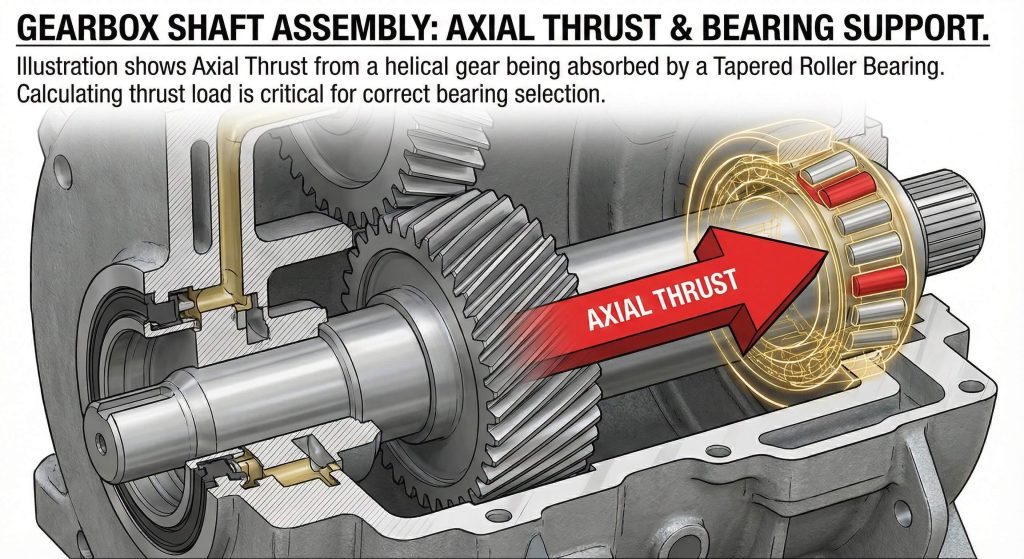
Is axial thrust managed by helical gear calculations?
Yes, helical gear calculations quantify the magnitude of axial thrust forces acting along the shaft, allowing you to select the appropriate bearings for your housing. Comprehensive analysis allows you to evaluate the tangent of the helix angle against the transmitted load to find the exact thrust value generated during operation. Understanding this magnitude is essential for preventing the gears from pushing themselves out of alignment and causing catastrophic gear failure.
Quantifying transmitted loads vs. thrust
In other words. The steeper the helix angle you choose, the higher the axial thrust you must manage with robust mechanical supports. This creates a trade-off where higher angles provide smoother operation but require much more robust thrust bearings to maintain system integrity.
- Thrust depends on the tangent of the helix angle.
- Transmitted load dictates the base force applied.
- Bearing selection prevents destructive axial displacement.
Key Takeaway: Quantifying axial thrust ensures that your gearbox housing and bearings are strong enough to withstand the lateral forces generated during power transmission.
| Helix Angle ($\beta$) | Load ($W_t$) | Thrust ($W_T$) | Bearing Requirement |
|---|---|---|---|
| 10° | 1000 N | 176 N | Ball Bearing |
| 25° | 1000 N | 466 N | Tapered Roller |
| 45° | 1000 N | 1000 N | Heavy Duty Thrust |
How do helical gear calculations link to bevel gearing?
They transition the math from cylindrical geometry to conical pitch surfaces, which is necessary for power transmission between intersecting shafts using helical gear calculations. When you apply these logic principles to bevel systems, you are essentially projecting the tooth path onto the surface of a sphere. This creates “octoid” tooth forms that mimic the rack-and-pinion relationship while allowing for a significant change in the axis direction.
Defining pitch angles for conical cones
Best of all. Bevel gears allow you to maintain high efficiency even when your drive shafts intersect at odd or non-standard angles. This is particularly useful in automotive differentials and right-angle industrial drives where space is at a premium and direction changes are necessary.
- Teeth converge at a single pitch apex point.
- Pitch angles are derived from the tooth ratio.
- Octoid forms ensure conjugate engagement at all times.
Key Takeaway: Bevel gearing logic bridges the gap between parallel shaft helical systems and the complex requirements of intersecting power paths.
| Parameter | Bevel Gear | Helical Gear |
|---|---|---|
| Pitch Surface | Conical | Cylindrical |
| Shaft Relation | Intersecting | Parallel or Skew |
| Tooth Form | Tapered Octoid | Uniform Involute |
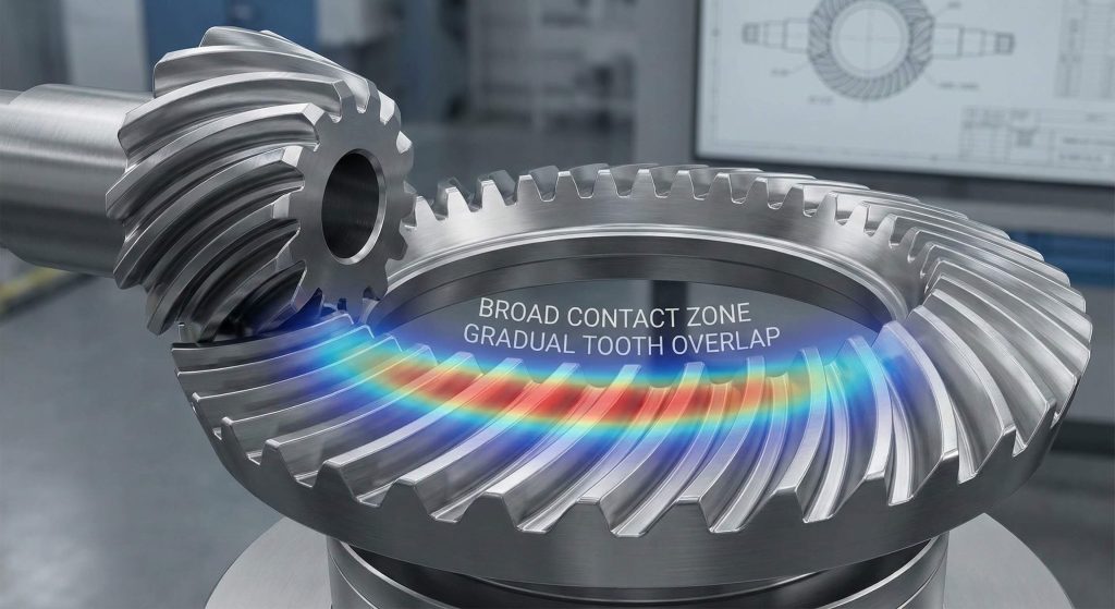
Which helical gear calculations apply to spiral bevels?
The central spiral angle must be calculated to ensure gradual tooth overlap and significantly quieter operation at high speeds compared to straight bevels during helical gear calculations. Utilizing the Gleason system involves profile shifts to balance strength between the gear and pinion while maximizing contact area. This overlap allows multiple teeth to be in contact at all times, distributing the load and reducing the vibration that causes mechanical wear.
The Gleason system for spiral bevels
You see. Spiral bevels are the industry choice for high-speed applications like automotive transmissions because they can handle massive loads without the loud “whine” typical of straight-cut gears. The gradual engagement prevents the impact loading that lead to premature tooth fatigue and failure.
- High tooth overlap ratio for silent operation.
- Requires perfectly matched hands for the pair.
- Supports higher rotational speeds than straight bevels.
Key Takeaway: Spiral bevel gears use complex helical logic to provide the smoothest possible power transition for intersecting shafts under heavy load.
| Feature | Spiral Bevel | Zerol Bevel | Straight Bevel |
|---|---|---|---|
| Spiral Angle | > 0° (Curved) | 0° (Curved) | 0° (Straight) |
| Noise Level | Lowest | Medium | Highest |
| Axial Thrust | High | Low | Minimal |
Can helical gear calculations improve miter gear sets?
They verify that 1:1 ratios maintain parallel top clearance and avoid undercutting through specific Gleason module standards in helical gear calculations. These calculations focus on right-angle drives where speed remains constant, meaning both gears are identical in size and tooth count for perfect symmetry. When manufactured with Coniflex crowning, these gears can tolerate small misalignments that would otherwise lead to edge loading and catastrophic failure during high-torque operation.
Maintaining right-angle drive stability
As a result. Miter gears are the most reliable way to change shaft direction without introducing the complexities of speed reduction or increased torque. They are perfect for timing systems and auxiliary drives where synchronization between components is the primary engineering goal.
- Identical gears ensure a perfect 1:1 ratio.
- Parallel top clearance improves aesthetics and wear.
- Crowning accommodates minor assembly tolerances.
Key Takeaway: Miter gears are a specialized solution for direction changes, relying on precise tooth geometry to ensure longevity and low maintenance.
| Feature | Gleason Miter | Standard Miter |
|---|---|---|
| Ratio | 1:1 | 1:1 |
| Whole Depth | 2.188 x Module | Variable |
| Profile Shift | None | None |
Conclusion
Engineering a high-performance transmission requires more than just picking parts from a catalog; it requires a deep mastery of metric gear technology and geometry. By solving the problems of axial thrust, noise pollution, and tooth undercutting through rigorous helical gear calculations, you can ensure your equipment operates at peak efficiency for years to come. Our brand vision is to provide reliable transmission components through genuine manufacturing and continuous improvement, supporting your maintenance and OEM needs globally. If you need technical support for your next project, please contact us today for a comprehensive engineering review.
Frequently Asked Questions
Q1: Can I use different helix angles for crossed helical gears?
Absolutely. While they can differ, the sum of both helix angles must perfectly match the physical shaft angle for the gears to engage properly without jamming.
Q2: What’s the best way to handle high axial thrust?
Generally, you should use tapered roller bearings or switch to a double helical (herringbone) design, which cancels out thrust forces internally through opposing teeth.
Q3: Can helical gear calculations predict system noise?
Higher tooth overlap ratios, derived from helix angle calculations, directly correlate to quieter operation and reduced vibration at high speeds.
Q4: What’s the best module for miter gear sets?
Typically, the module is selected based on your torque requirements; however, using the Gleason standard ensures the teeth are proportioned to prevent undercutting.
Q5: Do crossed helical gears have high efficiency?
Rarely. Because they rely on point contact and sliding motion, they are less efficient than parallel helical gears and are best suited for lower-load applications.