
A precise helical gear calculation is the mathematical foundation for converting geometric data between the normal and transverse planes to ensure high-performance power transmission. Mechanical engineers frequently face significant challenges regarding gear noise or premature component failure in high-load industrial environments. One tiny inaccuracy during the initial design phase leads to catastrophic operational breakdowns in heavy machinery and precision instrumentation. This technical documentation provides the solution through rigorous standards required for modern transmission systems using advanced metric gear technology principles.
How Do You Perform a Helical Gear Calculation?
You perform this calculation by defining the normal module and helix angle to derive the transverse values necessary for manufacturing and assembly. This essential process must distinguish between the normal system, which utilizes standard hobs, and the transverse system that relates directly to the rotation plane. Most industrial designs prioritize a helix angle between fifteen and thirty degrees to balance quiet operation against axial forces.
Primary Geometric Variables
To begin, you must establish the relationship between the two planes of the gear tooth. This involves selecting a module that matches your available tooling.
- Normal Module ($m_n$): The reference standard for tooth size.
- Helix Angle ($\beta$): The orientation of the teeth relative to the axis.
- Transverse Module ($m_t$): Calculated as $m_n / \cos \beta$.
But that’s not all.
Key Takeaway: Precise plane transformation is the non-negotiable foundation of any functional helical gear set.
| Parameter | Symbol | Helical Gear Calculation Formula | Technical Definition |
|---|---|---|---|
| Normal Module | $m_n$ | Reference Standard | The module in the plane normal to the tooth helix. |
| Pitch Diameter | $d$ | $z \cdot m_t$ | The diameter of the pitch circle where the gears mesh. |
| Base Diameter | $d_b$ | $d \cdot \cos \alpha_t$ | The diameter from which the involute profile is generated. |
Analysis: The relationship between the normal and transverse module is purely trigonometric. Even a one-degree deviation in the helix angle will shift the pitch diameter, potentially making the gear incompatible with standard spur gears or existing housings.
Why Is the Radial System Essential for a Helical Gear Calculation?
The radial system is essential for your helical gear calculation because it defines the tooth geometry within the plane of rotation, which is necessary for determining center distances. While the normal system allows for the use of standard cutters, the radial system provides the direct measurements needed for technicians checking parts with calipers. Choosing the radial system simplifies the calculation of the transverse pitch and makes spatial relationships more intuitive.
Pressure Angle Dynamics
Moving between systems requires you to adjust the pressure angle to maintain the correct involute form. This ensures the teeth engage without binding under load.
- Normal Pressure Angle: Usually set at 20 degrees for metric standards.
- Transverse Pressure Angle: Calculated to define the effective contact path.
- Tooling Compatibility: Ensures standard cutters can produce custom radial geometries.
Here is the kicker.
Key Takeaway: Radial metrics are the bridge between theoretical design and the physical spatial alignment of the gearbox.
| System Type | Primary Variable | Tooling Implication | Geometric Relationship |
|---|---|---|---|
| Normal System | Normal Module ($m_n$) | Standard Hobs | Based on the plane perpendicular to the tooth. |
| Radial System | Transverse Module ($m_t$) | Custom Shapers | Based on the plane of gear rotation. |
Analysis: The radial system acts as the “as-built” reference. While the normal system facilitates manufacturing, the radial system governs how the gears actually occupy space within a housing.
How Does Axial Thrust Affect Your Helical Gear Calculation?
Axial thrust affects your helical gear calculation by introducing longitudinal forces that require specialized bearing support to prevent catastrophic housing deformation. The magnitude of this axial component depends directly on the tangent of the helix angle you select during the initial design phase. Neglecting this variable will cause the bearings to overheat and fail prematurely due to excessive friction.
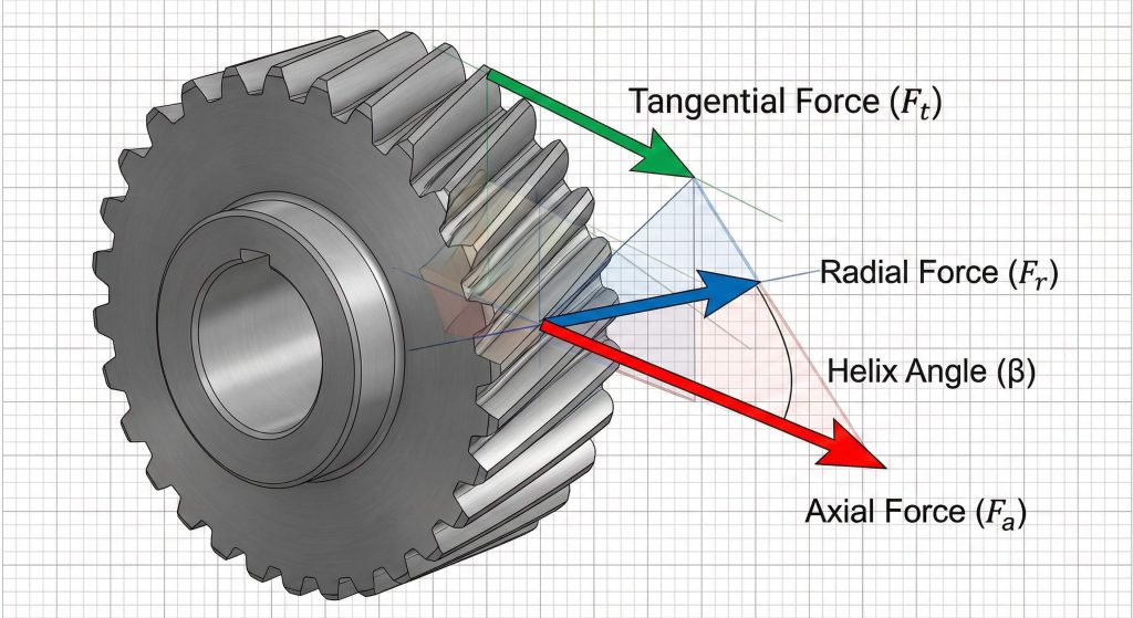
Force Vector Analysis
You must quantify every vector acting on the gear tooth to ensure the shaft can withstand the resulting moments. This involves calculating three distinct force components.
- Tangential Force ($F_t$): The primary load responsible for torque.
- Axial Force ($F_x$): The side load generated by the helix.
- Radial Force ($F_r$): The separation force pushing gears apart.
Think about this.
Key Takeaway: Every degree added to the helix angle increases axial load, necessitating more robust thrust bearing selection.
| Force Component | Calculation Formula | Impact Factor | Engineering Consequence |
|---|---|---|---|
| Tangential Force | $F_t = 2T / d$ | Torque Input | Primary power transmission force. |
| Axial Thrust | $F_x = F_t \cdot \tan \beta$ | Helix Angle | Side load requiring thrust bearings. |
Analysis: Balancing these forces is the central challenge of helical design. High helix angles provide quieter operation but create extreme axial loads that can deform lighter gearbox housings.
Can You Design Crossed Meshes Using a Helical Gear Calculation?
You can design these meshes using a helical gear calculation that manages non-parallel and non-intersecting shafts where the helix angles dictate the shaft angle. This configuration allows for unique packaging solutions in compact machinery where shafts must pass each other at various angles, typically ninety degrees. You must account for the fact that these gears have point contact rather than line contact, which limits their total torque capacity.
Contact and Friction Limits
Because these gears slide across one another, you must prioritize lubrication and material selection to avoid rapid wear. The contact is inherently more stressful than parallel meshes.
- Shaft Angle ($\Sigma$): The sum or difference of the two helix angles.
- Sliding Velocity: The speed at which teeth slide past each other.
- Point Contact: Limits the gear set to motion transfer rather than heavy torque.
Now, consider the impact.
Key Takeaway: Crossed helical gears excel in spatial flexibility but fail under high-torque loads due to concentrated point contact.
| Feature | Description | Technical Constraint | Design Mitigation |
|---|---|---|---|
| Shaft Relationship | Non-parallel | Requires shaft angle $\Sigma$ | Precision alignment of bores. |
| Efficiency | Lower (60% – 90%) | High sliding friction | Use synthetic EP lubricants. |
Analysis: Crossed meshes are a geometric compromise. They solve difficult packaging problems at the cost of mechanical efficiency and load-carrying capacity.
How Do You Determine the Velocity Ratio in a Helical Gear Calculation?
You determine the velocity ratio by dividing the number of teeth on the driven gear by the number of teeth on the driver pinion. This remains true regardless of the helix angle or the resulting pitch diameters of the gears involved. You can achieve various mechanical advantages within the same center distance by adjusting the helix angles of the two gears in your assembly.
Diameter vs. Ratio Optimization
In helical systems, you have the unique ability to change gear size without changing the ratio. This allows you to fit specific ratios into fixed housing dimensions.
- Tooth Ratio ($z_2 / z_1$): Defines the absolute speed change.
- Diameter Ratio: Can be modified by varying the helix angle.
- Center Distance: Controlled by the sum of the transverse radii.
It gets even better.
Key Takeaway: The tooth count dictates the speed ratio, while the helix angle dictates the physical size of the components.
| Variable | Influence on Ratio | Calculation Role | Mechanical Effect |
|---|---|---|---|
| Tooth Count ($z$) | Absolute | Direct Ratio Definition | Determines output RPM. |
| Helix Angle ($\beta$) | Diameter Only | Controls Center Distance | Changes gear size. |
Analysis: This decoupling of diameter and ratio is the primary reason engineers choose helical gears for custom gearboxes. It provides a level of design freedom that straight gears cannot match.
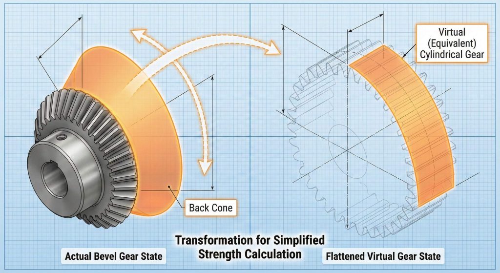
How Does Virtual Gear Theory Improve a Bevel Helical Gear Calculation?
Virtual gear theory improves accuracy in your helical gear calculation by mapping the three-dimensional bevel tooth onto a two-dimensional spur gear model on the back cone. This allows you to apply standard formulas for bending stress and load capacity to complex bevel gears. This approach simplifies the geometry into a model that is significantly easier to analyze mathematically.
Gleason System Standards
The Gleason system is the industry standard you will use for defining bevel tooth proportions and balancing strength. It ensures that both mating components have comparable durability.
- Outer Module ($m_{et}$): Used for initial gear sizing.
- Pitch Angle ($\delta$): Defines the cone angle for intersecting shafts.
- Virtual Teeth ($z_v$): The tooth count used for strength calculations.
Believe it or not.
Key Takeaway: Modeling the back cone distance as a virtual radius is the only reliable way to predict bevel gear fatigue.
| Dimension | Symbol | Calculation Basis | Practical Application |
|---|---|---|---|
| Back Cone | $r_v$ | $r / \cos \delta$ | Creates the virtual spur model. |
| Pitch Angle | $\delta$ | $\tan \delta = z_1 / z_2$ | Defines the shaft cone. |
Analysis: By treating the bevel tooth as a virtual spur tooth, you can use well-established AGMA or ISO standards to verify the design. This reduces the risk of failure in intersecting shaft applications.
Why Is Spiral Angle Critical in a Helical Gear Calculation?
The spiral angle is critical because it determines the overlap ratio and the gradual engagement required for quiet operation in high-speed bevel systems. Unlike straight bevels, where teeth enter the mesh instantaneously, spiral teeth enter gradually, which significantly reduces vibration. This refined calculation must account for the direction of thrust forces to ensure the gears do not bind during operation.
Curvature and Noise Reduction
You must select a spiral angle that provides enough overlap to distribute the load across multiple teeth simultaneously. This is the secret to high-load capacity in automotive differentials.
- Overlap Ratio: Increased by higher spiral angles.
- Contact Path: Curved to follow the cone surface.
- Vibration Dampening: Gradual entry eliminates the “hammering” effect.
What does this mean for you?
Key Takeaway: Spiral geometry trades increased axial thrust for a massive reduction in peak contact stress and operational noise.
| Factor | Straight Bevel | Spiral Bevel | Technical Advantage |
|---|---|---|---|
| Engagement | Instantaneous | Gradual | Massive noise reduction. |
| Load Capacity | Standard | High (+30%) | Better load distribution. |
Analysis: Spiral bevels are the gold standard for high-speed power transmission. While the math is more complex, the performance gains in noise and longevity are undeniable.
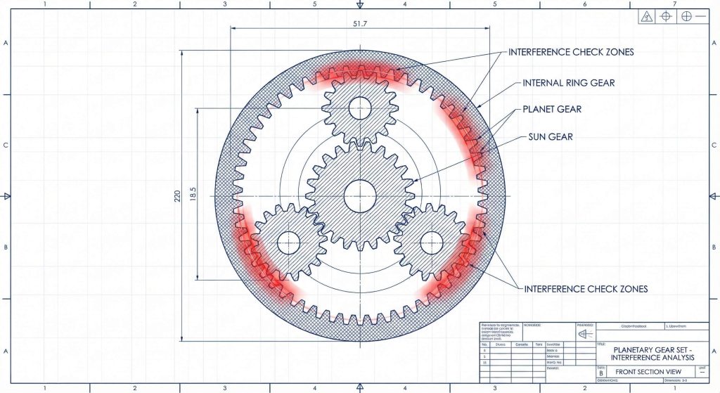
How Do You Handle Planetary Stages in a Helical Gear Calculation?
You handle planetary stages in your helical gear calculation by inverting sign conventions for internal diameters and subtracting the pinion radius from the internal ring gear radius. This configuration is essential for achieving high torque density in compact volumes like robotics. You must also account for unique interference issues, such as fillet interference, where the pinion teeth might clip the roots of the internal gear.
Internal Mesh Constraints
Your design must ensure that all planet gears share the load equally to prevent premature failure. This requires extremely tight tolerances on the carrier and internal teeth.
- Internal Gear: The outer ring of the planetary stage.
- Center Distance: The difference between the pitch radii.
- Trochoidal Interference: Prevented by maintaining a tooth count difference.
You might be wondering.
Key Takeaway: Internal helical meshes require rigorous trochoidal clearance checks to prevent tooth tip clipping during engagement.
| Component | Position | Calculation Convention | Assembly Role |
|---|---|---|---|
| Internal Gear | Outside | $d = z \cdot m_t$ (Positive) | Outer ring stage. |
| Center Distance | Offset | $a = (d_2 – d_1) / 2$ | Radial difference. |
Analysis: Planetary systems offer the highest torque-to-weight ratio. However, the internal helical mesh is sensitive to geometric interference, requiring precise profile shifting.
Can You Optimize Worm Meshes with a Helical Gear Calculation?
You can optimize these meshes by treating the worm as a gear with an extremely high helix angle and prioritizing the lead angle for efficiency. In this specialized mesh, the driver is a screw-like worm that typically has between one and four “starts.” The calculation for a worm mesh must also account for much lower efficiency due to the pure sliding action of the teeth.
Self-Locking and Reduction Logic
Many worm sets are designed to be self-locking, meaning the wheel cannot drive the worm, providing a safety feature for lifting equipment. This occurs when the lead angle is smaller than the friction angle.
- Lead ($L$): The axial distance the thread travels in one revolution.
- Starts: The number of individual threads on the worm.
- Self-Locking: Controlled by the relationship between lead angle and friction.
The reality is simple.
Key Takeaway: Worm gears provide massive reduction and safety braking through lead angle management.
| Metric | Helical Gear | Worm Mesh | Operational Impact |
|---|---|---|---|
| Motion Type | Rolling/Sliding | Pure Sliding | Worms generate more heat. |
| Max Ratio | ~10:1 | ~100:1 | High reduction in small space. |
Analysis: Worm gears are unique because they convert rotary motion into high torque with a built-in safety brake. The lead angle is the single most important variable for both efficiency and safety.
How Does the Gleason System Refine Your Helical Gear Calculation?
The Gleason system refines your helical gear calculation by using profile shift coefficients to balance root strength and prevent undercutting on small pinions. By shifting the profile, you can make the pinion teeth thicker at the root where they are naturally weakest. A refined model using Gleason logic significantly increases the fatigue life of the entire gear set.
Profile Shift Strategies
You use the coefficient $x$ to determine how much the cutting tool is shifted from the standard pitch line. This optimization allows you to use standard tooling to create high-performance custom geometries.
- Positive Shift ($+x$): Increases root thickness and prevents undercutting.
- Negative Shift ($-x$): Adjusts center distance for existing housings.
- Balanced Shift: Equalizes wear to maximize service life.
Make no mistake.
Key Takeaway: Profile shifting is the primary tool for saving small pinions from geometric failure and undercutting.
| Shift Type | Effect on Pinion | Calculation Goal | Practical Benefit |
|---|---|---|---|
| Positive Shift | Increases Root | Prevent Undercutting | Improves pinion strength. |
| Negative Shift | Decreases Root | Adjust Distance | Fits existing bores. |
Analysis: Profile shifting is not an “extra” step; it is a requirement for any gear set with low tooth counts. It ensures the involute profile remains functional and strong under heavy loads.

Frequently Asked Questions
Can I use standard spur gear hobs for helical gear manufacturing?
Yes, you can use standard hobs for the normal system, provided your helical gear calculation correctly translates the normal module to the required transverse dimensions for the finished gear.
What’s the best helix angle for a balance between noise and efficiency?
Most industrial applications find that an angle between 15 and 25 degrees offers the best compromise, providing significant noise reduction without creating unmanageable axial thrust loads.
How do I know if my gear set will be self-locking?
You can determine this by checking if the lead angle of the worm is significantly smaller than the friction angle of the mating materials, typically occurring at angles below 5 degrees.
Can I increase the load capacity of a gear set without changing its size?
Yes, you can increase capacity by applying a positive profile shift to the pinion and utilizing a spiral or helical tooth path to increase the contact ratio.
What’s the best way to manage heat in a crossed helical gear set?
The best approach involves using synthetic extreme-pressure (EP) lubricants and ensuring the housing has adequate surface area or active cooling to dissipate the heat from sliding friction.
Conclusion
In summary, we have scrutinized the intricate mathematical landscape of gear design across various configurations. The most critical insight is that a precise geometric transformation between the normal and transverse planes remains the non-negotiable foundation for all high-performance systems. Engineers must prioritize the quantification of axial thrust and the application of profile shifts to guarantee both mechanical integrity and quiet operation. To optimize your next project or to discuss custom manufacturing solutions, please contact us today.