Finding the perfect balance between compact design and high torque transmission is a constant battle for mechanical engineers and procurement managers. You are likely dealing with limited space in your machinery but still require massive power reduction and reliable holding capabilities, a combination that standard gear systems often fail to deliver. This mismatch frequently leads to bulky designs, hidden efficiency costs, or insufficient braking power that compromises safety. The solution lies in mastering the art of worm gearing. At Yantong Tech, we understand that reliability is engineered, not guessed, which is why we provide precision-ground worm gears that solve these exact transmission challenges for clients globally.
1. Understanding the Fundamentals and Worm Gear Formula History
What Defines a Worm Drive System?
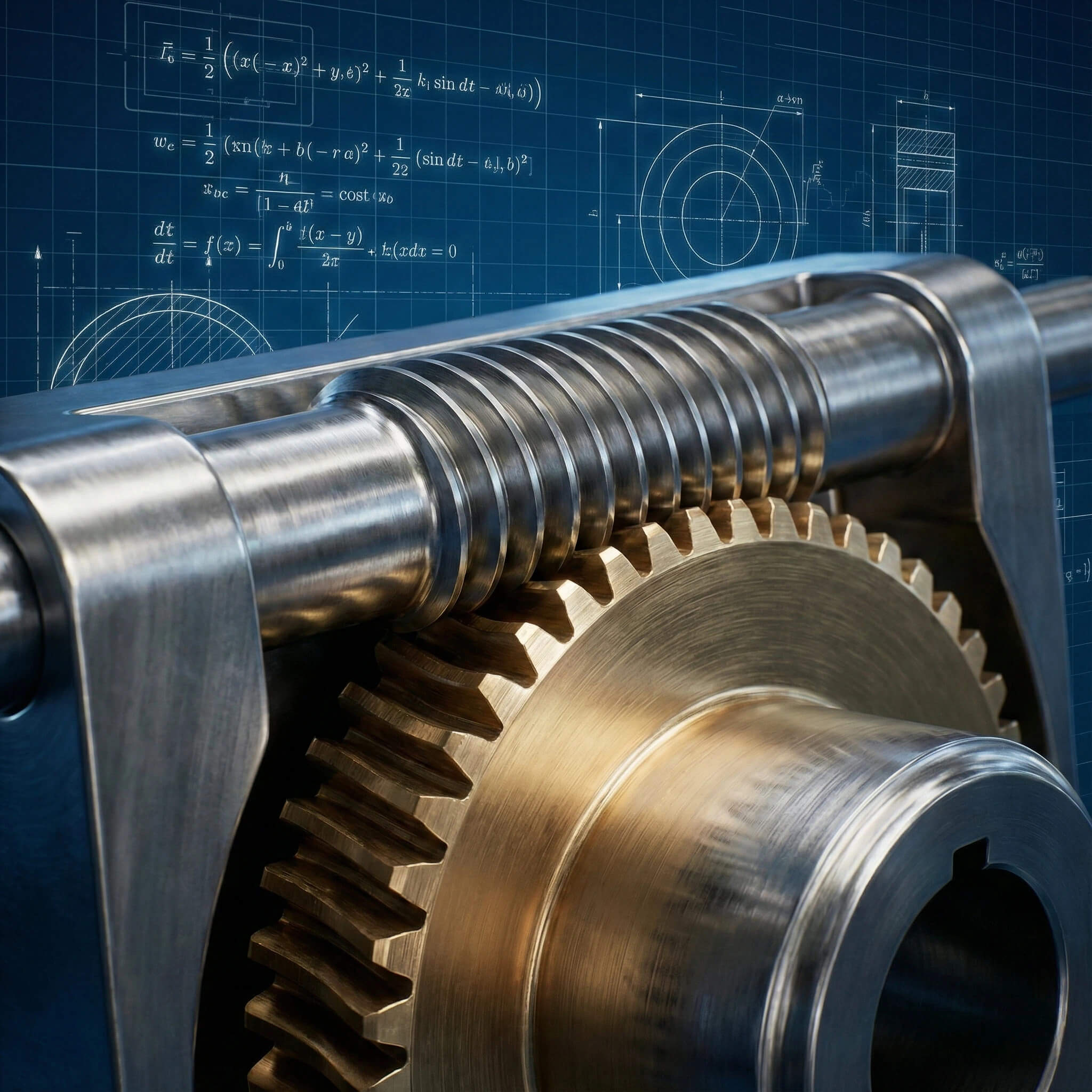
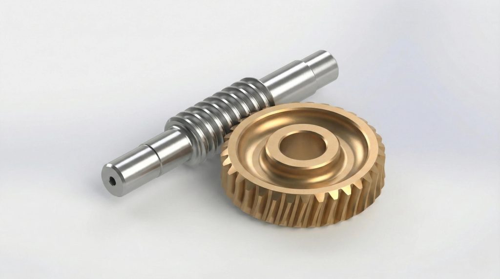
A worm drive is a compact gear arrangement where a screw-like worm meshes with a gear wheel to transmit motion between non-intersecting shafts. This unique setup converts rotational motion into linear movement or reduced speed with high torque. Key components include:
- The Worm: A threaded shaft acting as the driver.
- The Worm Wheel: A concave gear acting as the driven element.
- Shaft Angle: Typically arranged at 90 degrees.
Here is the deal: While the concept dates back to Archimedes, modern applications require a deep understanding of the worm gear formula to ensure efficiency and longevity.
How Did the Endless Screw Evolve?
The “endless screw” transitioned from ancient wooden irrigation devices to precision steel components during the Industrial Revolution. Modern manufacturing now demands micron-level tolerances to manage the sliding friction inherent in the design. Evolution milestones include:
- Ancient Greece: Wooden mechanisms for water lifting.
- Industrial Era: Metal alloys for heavy machinery.
- Modern Era: Precision grinding for robotics and automotive EPS.
What Distinguishes Gear Configurations?
Engineers must choose between three primary configurations based on load requirements and the specific worm gear formula applied to the contact area. You might be wondering which type fits your project best. The main types are:
- Non-Throated: Point contact, lowest load capacity.
- Single-Throated: Worm wheel wraps worm; line contact (Industry Standard).
- Double-Throated: Both wrap each other; highest load, requires extreme precision.
Key Takeaway
Worm gearing is a sliding-contact mechanism that converts rotational motion into high-torque output at 90 degrees. While the concept is ancient, modern reliability depends on choosing the right configuration—non-throated, single-throated, or double-throated—based on your specific load requirements and understanding the historical evolution of the technology.
2. Applying the Critical Worm Gear Formula for Design
How to Calculate the Reduction Ratio?
The most fundamental calculation in the worm gear formula set is the speed reduction ratio ($i$), which dictates output torque. Unlike spur gears, you calculate this by comparing the worm wheel teeth to the worm starts.
- Formula: $i = \frac{z_2}{z_1}$
- $z_2$: Number of teeth on the worm wheel.
- $z_1$: Number of starts (threads) on the worm.
Determining the Lead Angle Correctly?
The lead angle ($\gamma$) is the geometric secret to balancing efficiency and self-locking capabilities in your design. A higher lead angle generally improves efficiency but reduces the self-locking effect.
- Formula: $\tan(\gamma) = \frac{m \times z_1}{d_1}$
- $m$: Module of the gear.
- $d_1$: Pitch diameter of the worm.
Expert Analysis: Many engineers overlook the module ($m$) in favor of just looking at the ratio; however, the module determines tooth thickness and strength, so we always recommend optimizing the module to balance durability with housing size.
Why Does Center Distance Matter?
Calculating the exact center distance ($a$) is non-negotiable for ensuring the worm meshes correctly without binding or excessive backlash. But here is the kicker: an error here ruins the gearbox instantly.
- Formula: $a = \frac{d_1 + d_2}{2}$
- $d_1$: Worm pitch diameter.
- $d_2$: Wheel pitch diameter ($m \times z_2$).
Table 1: Essential Worm Gear Formulas and Parameters
| Parameter | Symbol | Basic Formula | Significance in Design |
|---|---|---|---|
| Gear Ratio | $i$ | $i = z_2 / z_1$ | Determines output speed and torque multiplication. |
| Pitch Diameter (Worm) | $d_1$ | $d_1 = q \times m$ | Defines the size of the driving screw; affects stiffness. |
| Pitch Diameter (Wheel) | $d_2$ | $d_2 = z_2 \times m$ | Defines the size of the output gear. |
| Center Distance | $a$ | $a = 0.5 \times (d_1 + d_2)$ | Critical for housing fit and proper meshing. |
| Lead Angle | $\gamma$ | $\tan(\gamma) = z_1 / q$ | High angle = High efficiency; Low angle = Self-locking. |
Key Takeaway
Mastering the worm gear formula is essential for a functional design. The relationship between the number of starts ($z_1$) and wheel teeth ($z_2$) dictates your ratio, while the lead angle ($\gamma$) acts as the control knob for balancing system efficiency against self-locking safety requirements.
3. Material Selection via the Worm Gear Formula
Why Use Dissimilar Metal Combinations?
The worm gear formula for friction dictates that sliding contact generates heat, necessitating dissimilar metals to prevent seizing. Steel-on-steel contact would result in rapid galling and catastrophic failure. Standard pairings include:
- Worm: Case-hardened alloy steel (e.g., 20CrMnTi).
- Wheel: Phosphor bronze or Nickel bronze.
- Reason: Bronze creates a sacrificial surface.
What Is the Role of Phosphor Bronze?
Phosphor bronze is selected for the worm wheel because it offers excellent wear resistance and a low coefficient of friction. It allows the gear to “bed in” with the harder steel worm during the initial operation cycles. Benefits include:
- Conformability: Adapts to the worm geometry.
- Lubricity: Natural resistance to friction.
- Thermal Conductivity: Helps dissipate heat.
How Do Steel Worm Shafts Function?
The worm shaft must be significantly harder than the wheel to drive the system effectively without deformation. This is where it gets interesting: Yantong Tech grinds these shafts to a mirror finish after heat treatment.
- Material: 18CrNiMo7-6 or SAE 8620.
- Hardness: 58-62 HRC (Rockwell C).
- Finish: Ground to ISO Class 6 to reduce friction.
Key Takeaway
Material selection is dictated by the tribology of sliding friction. You must pair a hardened steel worm with a softer bronze wheel to prevent galling, allowing the bronze to sacrificially wear and conform to the steel for a perfect, long-lasting mesh.
4. Why Choose Worm Gears Over Other Types?
What Are the Distinct Advantages?
Worm gears offer specific mechanical benefits that spur or bevel gears simply cannot match in a single stage. Ready for the good part? You can replace a bulky multi-stage gearbox with a single worm unit. Major pros include:
- High Ratio: Up to 100:1 reduction in one step.
- Silence: Sliding contact eliminates impact noise.
- Braking: Inherent resistance to back-driving.
How Does Efficiency Compare?
The trade-off for high torque is lower efficiency due to the sliding friction described by the worm gear formula. While a helical gear set might run at 98% efficiency, worm gears often vary. Comparison points:
- Helical: 95-99% efficient (Rolling contact).
- Worm: 50-90% efficient (Sliding contact).
- Heat: Worm gears require better cooling.
Expert Analysis: While efficiency is lower, the “cost” of power loss is often outweighed by the elimination of a secondary braking system; we advise clients to view the total system cost rather than just gearbox efficiency.
When Is Self-Locking Critical?
Self-locking is a safety feature where the load cannot drive the worm backward, essential for elevators and hoists. This phenomenon occurs when the friction angle exceeds the lead angle. Applications needing this:
- Conveyors: Prevents rollback on inclines.
- Lifts: Holds load if power fails.
- Solar Trackers: Resists wind loads.
Table 2: Comparison of Gear Types for Right-Angle or High-Reduction
| Feature | Worm Gear | Bevel Gear | Planetary Gear |
|---|---|---|---|
| Max Ratio (Single Stage) | High (up to 100:1) | Low (up to 6:1) | Medium (up to 10:1) |
| Efficiency | Low to Medium (50-90%) | High (95-98%) | High (95-98%) |
| Self-Locking | Yes (Design dependent) | No | No |
| Noise Level | Low (Silent sliding) | Medium | Medium to High |
| Cost | Moderate | Moderate to High | High |
Key Takeaway
Choose worm gears when you need massive speed reduction in a tight space, low noise, or self-locking safety. However, if your application involves extremely high speeds or requires maximum energy conservation, alternative gearing might be superior despite the larger footprint.
5. Industrial Applications of the Worm Gear Formula
How Does Automotive Use Worm Gears?
The automotive industry relies on the worm gear formula for compact torque multiplication in safety-critical systems. Electric Power Steering (EPS) is the prime example, where a small motor assists the driver. Key uses:
- EPS: Steering column assistance.
- Seat Adjusters: Smooth positioning.
- Torsen Differentials: Torque distribution.
Why Is Precision Vital in Robotics?
In robotics, the holding torque capability of a worm gear allows joints to remain static without consuming motor power. What’s the real story? This reduces battery drain and thermal load on the servo motors.
- Joint Actuators: Zero-backlash designs.
- Grippers: High force in small packages.
- Welding Arms: Rigid positioning.
What Role in Heavy Industry?
Heavy industries utilize the high reduction ratios to move massive loads with relatively small motors. The self-locking nature serves as a critical safety backup in mining and construction. Common machines:
- Conveyors: Moving raw materials.
- Gate Valves: Controlling pipeline flow.
- Winches: Lifting heavy loads.
Table 3: Industry Application Matrix
| Industry | Application | Why Worm Gear? |
|---|---|---|
| Automotive | Power Steering (EPS) | Smooth feel, compact, safety holding. |
| Material Handling | Conveyor Drives | High torque, prevents rollback (safety). |
| Construction | Elevators / Hoists | Compact high reduction, emergency braking. |
| Manufacturing | Rotary Tables | Precision indexing, minimal backlash. |
| Energy | Solar Trackers | Holds panels against wind load; slow accurate movement. |
Key Takeaway
From the precise movements of a robotic arm to the heavy lifting of a quarry conveyor, worm gears are the silent workhorses of industry. They solve specific engineering problems: holding loads against gravity, providing high torque from small motors, and ensuring safety through self-locking mechanics.
6. Analyzing Efficiency and Torque with the Worm Gear Formula
How to Calculate Output Torque?
Calculating torque ($T_{out}$) requires factoring in the efficiency losses derived from the worm gear formula. You cannot assume 100% transfer of power from the motor to the driven shaft.
- Formula: $T_{out} = T_{in} \times i \times \eta$
- $T_{in}$: Input torque.
- $\eta$: Efficiency (decimal).
What Influences Gear Efficiency?
Efficiency ($\eta$) is strictly tied to the lead angle and the coefficient of friction between the materials. Higher lead angles typically yield higher efficiency but reduce self-locking potential. Variables include:
- Lubrication: Synthetics improve $\eta$.
- Ratio: High ratios = lower $\eta$.
- Speed: Sliding velocity affects friction.
Expert Analysis: We caution engineers that “start-up efficiency” is always lower than “running efficiency” due to static friction; if you size your motor based only on running efficiency, the system may stall at start-up.
How to Manage Heat Generation?
Since lost power converts to heat, the thermal rating of the gearbox is often the limiting factor rather than mechanical strength. Proper cooling and lubrication are essential to prevent oil breakdown.
- Synthetic Oil: Resists high heat.
- Cooling Fins: Increase surface area.
- Fans: Forced air cooling.
Key Takeaway
Never ignore the efficiency variable ($\eta$) in your torque calculations. A high-ratio worm gear effectively “steals” motor power to generate heat, so you must oversize your motor slightly and ensure adequate cooling to compensate for these inherent losses.
7. Troubleshooting Common Issues via the Worm Gear Formula
What Causes Overheating Failures?
If a gearbox runs too hot, it is often a violation of the thermal limits calculated in the worm gear formula. Overheating leads to seal failure and oil oxidation. Common causes:
- Low Oil: Insufficient volume.
- Wrong Viscosity: Too thick or thin.
- Overloading: Exceeding design torque.
Why Does Pitting Occur?
Pitting on the bronze wheel indicates surface fatigue where the material stresses exceed its endurance limit. Here is the bottom line: If you see “glitter” in the oil, your gear is degrading.
- Shock Loads: Sudden impacts.
- Misalignment: Uneven contact.
- Material Fatigue: End of life cycle.
How to Fix Backlash Problems?
Backlash is the clearance between the mating teeth, which increases as the bronze wheel wears down. While some backlash is necessary for lubrication, excessive amounts ruin precision. Solutions:
- Wheel Replacement: Standard maintenance.
- Split Worms: Adjustable width design.
- Center Adjustment: Reducing distance (if capable).
Table 4: Troubleshooting Common Worm Gear Issues
| Symptom | Probable Cause | Corrective Action |
|---|---|---|
| Excessive Heat | Insufficient oil / High friction | Check oil level; switch to synthetic; check for overloading. |
| Grinding Noise | Bearing failure or contamination | Replace bearings; flush gearbox; check seals. |
| Bronze Flakes in Oil | Overload / Normal Wear | If excessive, check load alignment. Schedule wheel replacement. |
| Vibration | Misalignment of shafts | Re-align motor and load shafts; check coupling. |
| Seal Leakage | Pressure buildup / Worn seal | Clean breather vent; replace seals; check shaft surface. |
Key Takeaway
Maintenance is proactive, not reactive. Monitoring oil temperature and analyzing oil for bronze particles offers the best insight into the health of your gear set. Addressing heat and lubrication issues early prevents catastrophic failure and costly downtime.
Conclusion
Worm gearing remains a cornerstone of mechanical power transmission, offering a unique blend of high torque, compact size, and safety features that other gear types simply cannot match. Whether you are designing a precision robotic arm or a heavy-duty conveyor, understanding the interplay of the worm gear formula, material selection, and efficiency is vital for success.
However, design is only half the battle. The quality of manufacturing determines whether your equipment runs for a decade or fails in a month. Don’t let poor component quality compromise your brand’s reputation.
At Yantong Tech, we combine engineering expertise with state-of-the-art manufacturing to deliver worm gears that meet the rigorous standards of the global market. We are ready to review your drawings, optimize your designs using the correct formulas, and provide the reliable supply chain you deserve.
Ready to upgrade your transmission systems? Contact Yantong Tech today for a consultation or a quote on your precision gear needs.
FAQ
Q1: What is the main disadvantage of using worm gears compared to helical gears?
The main disadvantage is lower efficiency. Due to the sliding contact between the worm and the wheel, worm gears generate significantly more friction and heat than helical gears, which use rolling contact. This means they require more power to drive and often need better lubrication or cooling, especially at high reduction ratios.
Q2: How does the self-locking mechanism in worm gears work?
Self-locking works based on the friction angle and the lead angle of the worm. If the tangent of the lead angle is less than the coefficient of friction between the materials, the worm wheel cannot drive the worm backward. This creates a braking effect, preventing the load from reversing the direction of motion when power is cut.
Q3: Can I use worm gears for high-speed applications?
Generally, no. Worm gears are not recommended for very high-speed inputs (typically above 3000 RPM) because the high sliding velocity generates excessive heat that can break down the lubricant and cause rapid wear or seizure. For high speeds, bevel or helical gears are preferred.
Q4: Why are worm wheels typically made of bronze and worms of steel?
They are made of dissimilar metals to minimize friction and prevent galling (seizing) during the sliding contact. The steel worm is hardened to withstand the load, while the bronze wheel is softer and has natural lubricity. The bronze sacrifices itself slowly, allowing the two components to “bed in” and mate perfectly without damaging the critical worm shaft.
Q5: What is the typical efficiency range for a worm gear reducer?
The efficiency varies widely based on the ratio. Low-ratio units (e.g., 5:1 to 10:1) can achieve 85% to 90% efficiency. However, high-ratio units (e.g., 60:1 or 100:1) often drop to between 50% and 60% efficiency due to the shallow lead angle and increased friction.