Helical gear calculations involve determining the geometric dimensions and force vectors of gears with angled teeth to ensure smooth power transmission across parallel or intersecting shafts. Many engineers struggle with the complexity of transverse versus normal planes, leading to noise or mechanical interference in high-torque applications. By using a helical gear design calculator, you can simplify these intricate mathematical relationships and produce high-performance gear sets with absolute confidence.
Why calculate normal systems with a helical gear design calculator?
You should use a helical gear design calculator for normal systems because it allows you to standardize tooling by defining tooth geometry perpendicular to the helix. This approach is essential because the normal module and normal pressure angle must match the standard cutters used in manufacturing.
Here is the deal:
- Normal module ($m_n$) stays constant for standard cutters.
- Profile shift is usually applied in the normal plane.
- Virtual tooth numbers determine the beam strength.
Mastering the normal plane geometry
Think about it: you cannot ignore the difference between the physical tooth shape and its projection. When you follow a helical gear design procedure, you ensure the virtual number of teeth is high enough to avoid early fatigue.
Make no mistake:
- Higher helix angles increase the virtual tooth count.
- Normal pressure angles are typically set at 20 degrees.
- Tooth thickness is measured along the normal arc.
Summary of Normal System Parameters
| Parameter | Symbol | Definition |
|---|---|---|
| Normal Module | $m_n$ | Transverse Module × $\cos(\beta)$ |
| Normal Pressure Angle | $\alpha_n$ | $\arctan(\tan(\alpha_t) × \cos(\beta))$ |
| Virtual Tooth Number | $z_v$ | $z / \cos^3(\beta)$ |
Analyzing these parameters shows that the normal system is the foundation for tool selection and strength verification.
Key Takeaway: The normal system is the industrial standard for helical gear design because it aligns with common manufacturing tools.
How to compute radial dimensions with a helical gear design calculator?
A helical gear design calculator computes radial dimensions to help you determine the actual pitch diameters and center distances within the plane of rotation. While the normal plane is for tooling, the radial plane (or transverse system) is what dictates how your gears fit inside a gearbox housing.
The best part?
- Transverse module ($m_t$) is directly related to pitch diameter.
- Center distances are calculated using radial values.
- You can easily find the accurate helix angle dimensions for any specific housing.
Managing transverse pressure angles
Believe it or not, the pressure angle changes significantly when you move from the normal plane to the radial plane. You must account for this shift to ensure the gears mesh correctly without binding or excessive backlash.
Simply put:
- Transverse pressure angle is always larger than normal pressure angle.
- It determines the contact ratio in the plane of rotation.
- Radial pitch is essential for timing and synchronization.
Radial System Calculation Summary
| Feature | Symbol | Radial Formula |
|---|---|---|
| Transverse Module | $m_t$ | $m_n / \cos(\beta)$ |
| Pitch Diameter | $d$ | $z \times m_t$ |
| Transverse Pitch | $p_t$ | $\pi \times m_t$ |
The radial system is indispensable for spatial layout and ensuring the physical gear fits the intended center distance.
Key Takeaway: Radial calculations translate theoretical tooth shapes into physical dimensions necessary for gearbox assembly.
Can you design double helical meshes with a helical gear design calculator?
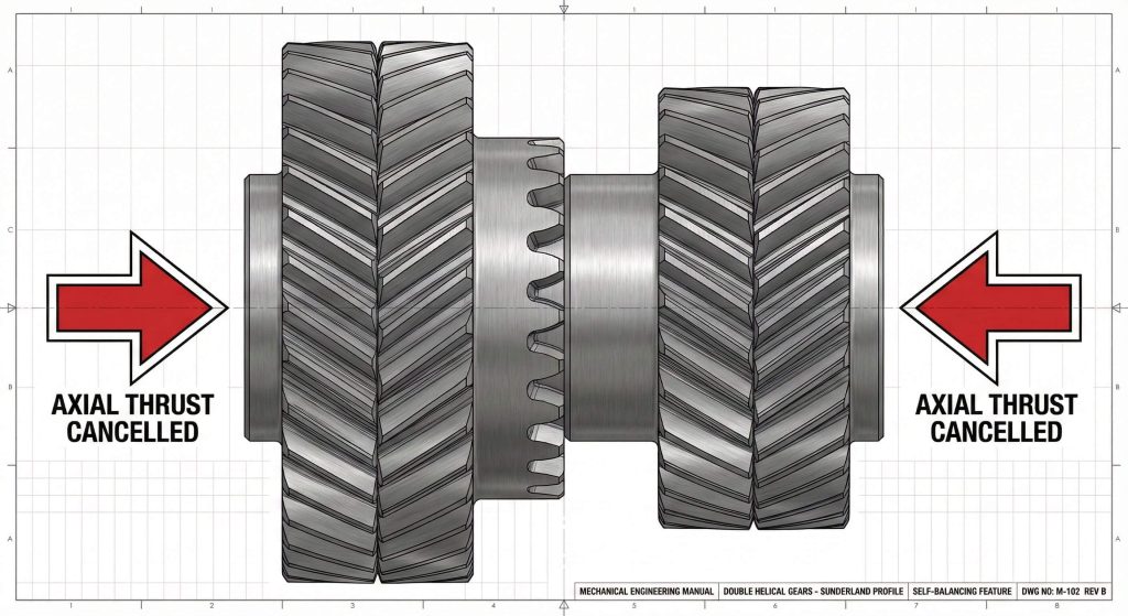
You can design double helical meshes with a helical gear design calculator by specialized formulas that account for the unique Sunderland tooth profile and axial load cancellation. These gears, often called herringbone gears, consist of two helical paths with opposite hands to neutralize thrust.
Look at it this way:
- Double helical gears eliminate the need for heavy thrust bearings.
- They allow for much higher helix angles than single helical gears.
- Alignment sensitivity is the main tradeoff for this stability.
Sunderland tooth profile adjustments
Wait, there is more to these gears than just doubling the width. When you analyze helical gear product specifications, you will find that Sunderland gears use specific addendum and whole depth constants.
It gets better:
- Radial pressure angles are often standardized at 20 degrees.
- The central groove width must be calculated for tool clearance.
- Helix angles are frequently set at 22.5 degrees for balance.
Double Helical vs. Single Helical
| Metric | Single Helical | Double Helical |
|---|---|---|
| Axial Thrust | High (Requires Thrust Bearing) | Zero (Self-Cancelling) |
| Power Capacity | Moderate | Very High |
| Manufacturing Cost | Standard | Premium |
Double helical designs are the gold standard for heavy-duty industrial drives where axial forces could damage standard housings.
Key Takeaway: Double helical gears provide superior power density by mechanically cancelling out problematic axial thrust forces.
Are helical rack calculations easier with a helical gear design calculator?
A helical gear design calculator makes helical rack calculations easier by automatically converting circular rotation into linear displacement based on the radial pitch. This is critical for high-speed linear motion systems where you need the smoothness of helical teeth without the vibration of spur racks.
Here is why it matters:
- Linear displacement per revolution is an exact calculation.
- The rack must have the opposite hand of the mating gear.
- You can optimize the helix angle to achieve integer travel values.
Matching the hand and angle
You might wonder how a flat rack can maintain a helix angle. The teeth are cut at an angle across the face of the rack, and you must ensure the normal module of the rack matches your pinion exactly.
Believe it or not:
- Misaligned hands will prevent the gear from seating.
- Normal pressure angles must be identical for proper contact.
- Helical racks offer much higher load-carrying capacity than spur racks.
Helical Rack Displacement Metrics
| Property | Calculation Basis | Result |
|---|---|---|
| Linear Travel ($l$) | $z \times p_t$ | Displacement per 1 revolution |
| Normal Pitch | $p_n$ | Distance between teeth in normal plane |
| Hand Requirement | Opposite of Pinion | Required for parallel meshing |
These calculations ensure that your linear actuators operate with the precision and quietness required for modern automation.
Key Takeaway: Helical racks must precisely match the pinion’s normal module while maintaining the opposite hand for successful engagement.
Is shaft angle vital in a helical gear design calculator for crossed meshes?
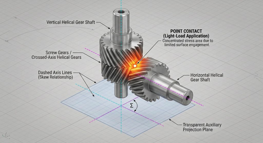
Shaft angle is the most vital input in a helical gear design calculator for crossed meshes because it determines the sum of the helix angles for non-parallel shafts. Unlike standard parallel gears, crossed helical gears (screw gears) transmit power between skew shafts that do not intersect.
Now for the secret:
- The velocity ratio depends on tooth counts, not pitch diameters.
- You can have different helix angles on the gear and pinion.
- Point contact limits these gears to light-load applications.
Managing skew shaft velocity ratios
Think about it: in a crossed mesh, the pitch diameters can be adjusted independently of the gear ratio by changing the helix angles. This flexibility allows you to fit gears into tight spaces where traditional ratios would be impossible.
Simply put:
- Gear ratio $i = z_2 / z_1$.
- Normal modules must be identical for both gears.
- Helix angles can be tweaked to meet a specific center distance.
Crossed Helical Mesh Criteria
| Requirement | Parallel Helical | Crossed Helical |
|---|---|---|
| Hand Type | Opposite (L/R) | Usually Same (R/R or L/L) |
| Shaft Alignment | Parallel | Non-parallel / Non-intersecting |
| Contact Type | Line Contact | Point Contact |
Crossed helical gears offer incredible design freedom but require careful thermal management due to higher sliding velocities.
Key Takeaway: Crossed helical gears use identical normal modules to connect skew shafts at virtually any angle.
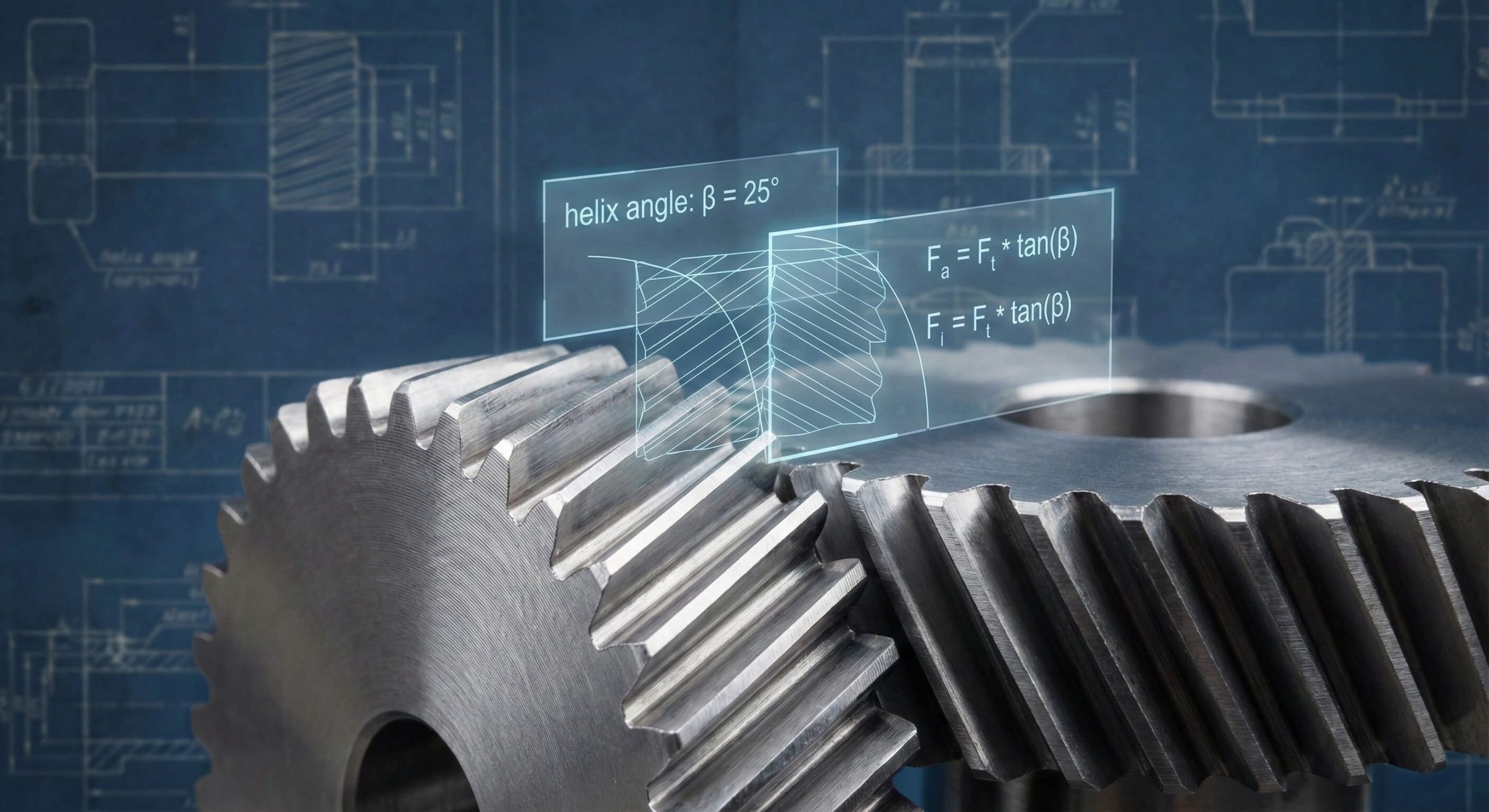
How to calculate axial thrust with a helical gear design calculator?
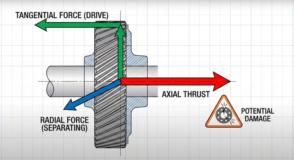
You use a helical gear design calculator to calculate axial thrust by multiplying the tangential load by the tangent of the helix angle. This calculation is mandatory because axial thrust is a side effect of helical teeth that can destroy standard bearings if not properly managed.
Look at it this way:
- Tangential load ($W_t$) drives the rotation.
- Axial thrust ($W_T$) pushes the gear along the shaft.
- Bearing selection must account for this combined load.
Selecting bearings for thrust loads
Make no mistake: if you ignore the thrust vector, your assembly will fail. You must choose tapered roller bearings or angular contact bearings to handle the forces generated by high helix angles.
Here is the deal:
- Higher helix angles provide smoother operation.
- Higher helix angles also generate much higher thrust forces.
- The direction of thrust depends on the hand and rotation direction.
Axial Thrust Force Analysis
| Force Vector | Calculation | Impact |
|---|---|---|
| Tangential ($W_t$) | Transmitted Torque / Radius | Primary driving force |
| Axial ($W_T$) | $W_t \times \tan(\beta)$ | Side load on bearings |
| Radial ($W_r$) | $W_t \times \tan(\alpha_t)$ | Separating force between shafts |
Accurate thrust calculations are the difference between a reliable machine and one that requires constant bearing replacements.
Key Takeaway: Axial thrust is directly proportional to the helix angle and must be supported by specialized bearing arrangements.
Why is bevel geometry unique in a helical gear design calculator?
Bevel gear geometry is unique in a helical gear design calculator because the teeth are tapered and converge toward a central pitch apex. You are essentially working with the surfaces of intersecting cones rather than cylinders, which changes every dimensional reference point.
Wait, there is more:
- All dimensions are referenced to the outer end (the “heel”).
- The pitch cone angle is determined by the gear ratio.
- The tooth profile is technically an “octoid” rather than a true involute.
Understanding the pitch apex intersection
You must ensure that the axes of your bevel gears intersect perfectly at the pitch apex. If the apexes do not align, the gears will experience localized loading and rapid tooth wear.
Make no mistake:
- Straight bevel gears are best for low-speed applications.
- The crown gear is the basic reference for all bevel systems.
- Face width is limited to prevent “toe” interference.
Bevel Gear Geometry Components
| Component | Function | Significance |
|---|---|---|
| Pitch Apex | Intersection point | Defines the cone geometry |
| Heel | Outer end of tooth | Reference point for module |
| Toe | Inner end of tooth | Limit of effective face width |
Analyzing bevel geometry requires a shift in perspective from 2D circles to 3D cone segments.
Key Takeaway: Bevel gear dimensions are tapered, requiring all measurements to be standardized at the outer heel of the tooth.
Does a helical gear design calculator prevent Gleason undercut?
A helical gear design calculator prevents Gleason undercut by automatically applying a positive profile shift to pinions with low tooth counts. This system is the industry standard for straight bevel gears because it balances tooth strength and ensures the top clearance remains parallel.
Think about it:
- Undercutting weakens the tooth root significantly.
- Gleason systems use a 20-degree pressure angle to improve durability.
- Pinions are enlarged while gears are reduced to maintain the center.
Parallel top clearance advantages
Believe it or not, standard bevel gears have variable clearance that is smaller at the toe. The Gleason system fixes this by making the outer cone elements parallel, ensuring a consistent gap across the entire tooth length.
It gets better:
- Parallel clearance allows for better lubricant flow.
- It reduces the risk of interference during thermal expansion.
- The system is optimized for “Coniflex” crowning.
Gleason System Standards
| Feature | Specification | Result |
|---|---|---|
| Working Depth | $2.000 \times m$ | Standardized tooth height |
| Whole Depth | $2.188 \times m$ | Includes root clearance |
| Profile Shift | Positive on Pinion | Prevents undercutting |
The Gleason system is essential for any engineer designing high-torque intersecting shaft drives.
Key Takeaway: The Gleason system uses profile shifting to eliminate undercut and provides parallel top clearance for superior mesh quality.
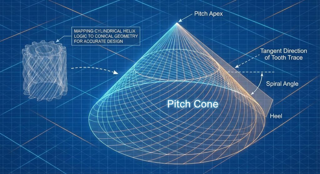
Can you optimize spiral bevels with a helical gear design calculator?
You can optimize spiral bevels with a helical gear design calculator by determining the central spiral angle needed for maximum tooth overlap. Spiral bevel gears are the high-performance evolution of straight bevels, offering quieter operation and much higher load capacities due to their curved teeth.
Here is the deal:
- Two or more teeth are always in contact.
- They transmit motion much more smoothly at high speeds.
- Hand matching is critical (one left-hand, one right-hand).
Balancing overlap and thrust forces
You might wonder why we don’t use spiral bevels for everything. While they are superior in performance, they generate significant thrust loads that require robust housing and specialized bearing support.
Simply put:
- Spiral angle ($\beta_m$) is typically 35 degrees.
- They use a stub tooth system for extra strength.
- Zerol bevels are a special version with zero spiral angle.
Spiral Bevel Performance Metrics
| Metric | Straight Bevel | Spiral Bevel |
|---|---|---|
| Noise Level | High | Very Low |
| Load Capacity | Standard | Very High |
| Speed Limit | < 300 m/min | > 300 m/min |
Spiral bevel gears are the preferred choice for automotive differentials and high-speed aerospace gearboxes.
Key Takeaway: Spiral bevel gears utilize tooth overlap to provide the quietest and strongest transmission possible between intersecting shafts.
How to verify miter gears with a helical gear design calculator?
You verify miter gears with a helical gear design calculator by confirming a 1:1 speed ratio and a 90-degree shaft angle. Since miter gears are identical pairs, the pitch cone angle for both the pinion and the gear must always be exactly 45 degrees.
Think about it:
- Miter gears do not change torque or speed.
- They are used strictly to change the direction of motion.
- No profile shift is required because the teeth are identical.
Simplifying the 1:1 drive assembly
Believe it or not, miter gears are the easiest bevel gears to calculate because you only need to define one gear to know the specs for the whole pair. This simplicity makes them ideal for manual drives and simple redirection tasks.
Make no mistake:
- Shafts must be exactly 90 degrees apart.
- Backlash must be set carefully during mounting.
- They are often available as standard stock components.
Miter Gear Reference Table
| Parameter | Value for Miter | significance |
|---|---|---|
| Speed Ratio | $1:1$ | No speed change |
| Pitch Angle ($\delta$) | $45^\circ$ | Symmetrical mesh |
| Shaft Angle ($\Sigma$) | $90^\circ$ | Right-angle drive |
Verification ensures that your miter gear pair will operate without noise or vibration in right-angle applications.
Key Takeaway: Miter gears are specialized 1:1 bevel gears where both components share a 45-degree pitch cone angle.
Frequently Asked Questions
Can I use a helical gear design calculator for internal gear sets?
Yes, but you must account for the negative tooth curvature and the potential for tip interference between the pinion and the internal teeth.
What’s the best way to choose between a normal and radial system?
Always choose the normal system for manufacturing and tool selection, while the radial system should be used for gearbox layout and center distance checks.
How do I know if my crossed helical gears will have enough contact?
Crossed helical gears have point contact, so you should only use them for auxiliary drives or low-torque timing applications where high load is not a factor.
Can I mix a right-hand helical gear with another right-hand gear?
Only if the shafts are crossed; for parallel shafts, you must pair a right-hand gear with a left-hand gear to achieve proper meshing.
What’s the best pressure angle for high-torque bevel gears?
A 20-degree pressure angle is the industry standard for Gleason and spiral bevel systems to maximize tooth root strength and durability.
Precision Engineering for a Motion-Driven World
Mastering helical and bevel gear technology is about more than just numbers; it is about ensuring the reliability of the machines that power our world. From the quiet operation of spiral bevels to the zero-thrust balance of double helical drives, every calculation serves a specific mechanical purpose. At GearAide, we are dedicated to providing the analytical tools and technical insights that turn complex geometry into seamless performance. Our vision is to empower engineers with the precision they need to build a more efficient and durable future. If you are ready to optimize your next gear project, contact us today to explore our full suite of design solutions and expert support.