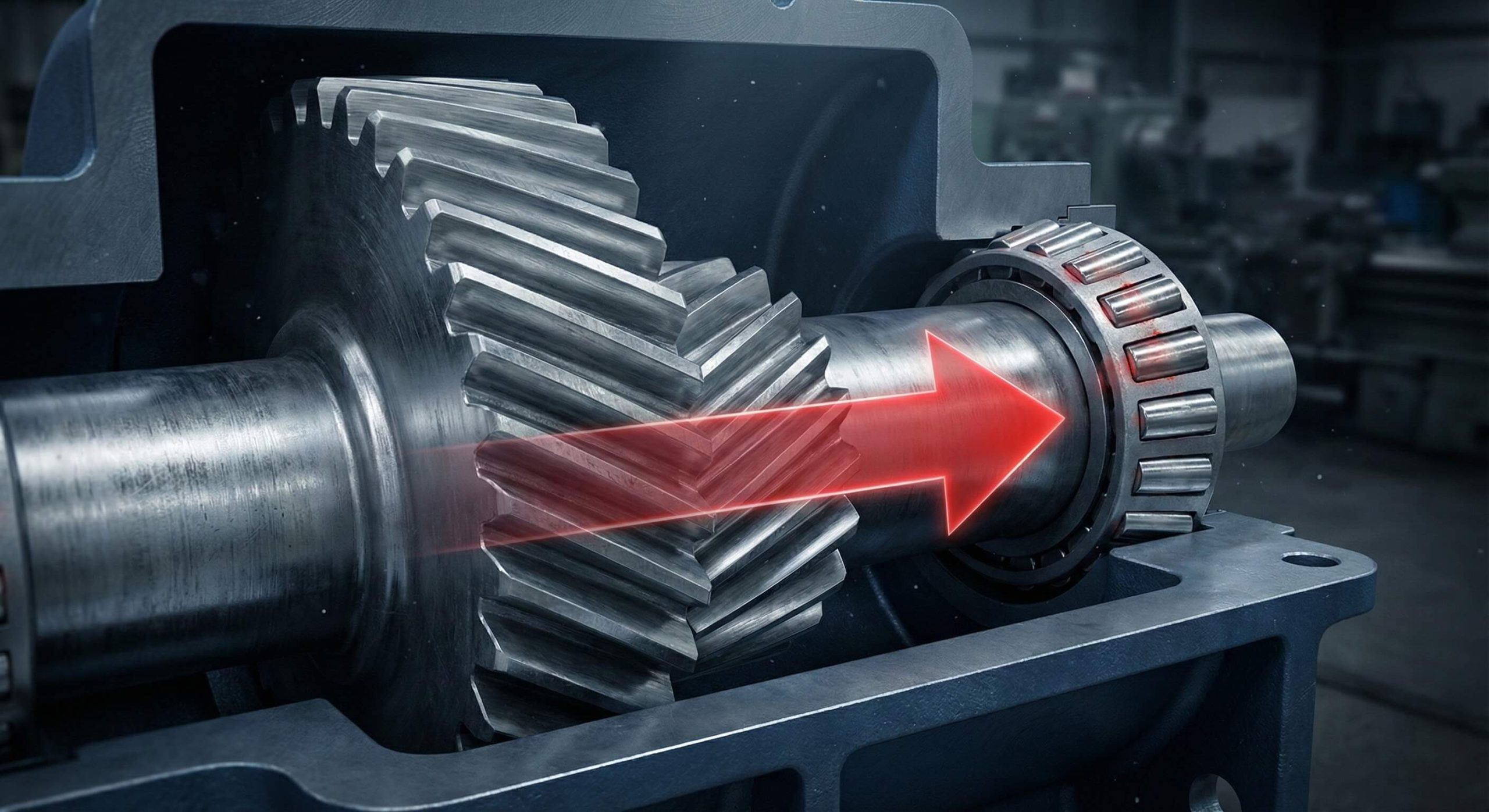
Angled tooth geometry creates sliding vectors along shafting during heavy rotation cycles, which causes axial thrust in your gearbox. Your machinery faces massive vibration or bearing destruction without professional helical gear thrust direction management right now. My specialized expertise provides definitive mechanical solutions regarding these complex axial forces today. Trust our technical gear knowledge regarding industrial power transmission.
What defines the helical gear thrust direction?
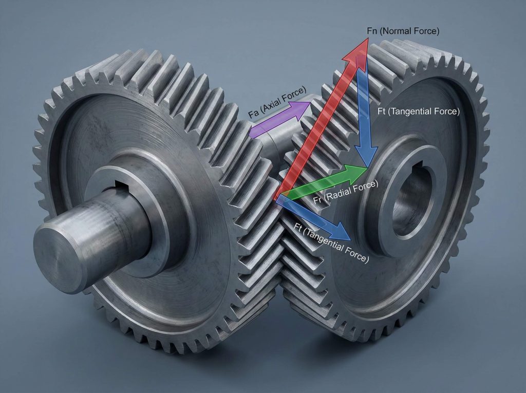
Helix angle orientation strictly dictates helical gear thrust direction while tooth mesh generates significant sideways pressure within various industrial power transmission systems today. You observe massive axial force whenever sliding contact occurs along slanted profiles during heavy rotation cycles inside complex machinery setups. Those vectors emerge because perpendicular contact normal forces split into three distinct mechanical components inside gearboxes requiring careful alignment by maintenance personnel.
How teeth interact with shafts
Here is the deal:
- Angled tooth surfaces create sliding vectors.
- Normal force splits into axial components.
- Helix direction determines lateral movement path.
Managing axial vectors
Think about it:
- Opposite hands work for parallel.
- Same hands work for crossing.
- Reversing hand flips thrust path.
Key Takeaway: Axial thrust exists because gear teeth act like screw threads against their mating partners during high-torque transmission events.
| Force Component | Directional Path | Impact Level |
|---|---|---|
| Tangential | Circular | Primary Drive |
| Radial | Perpendicular | Shaft Flex |
| Axial | Parallel | Bearing Load |
Careful analysis shows that axial forces require specialized containment to prevent total mechanical failure.
Does helix angle change helical gear thrust direction?
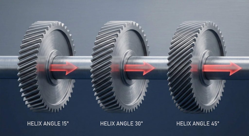
The specific helix angle magnitude determines helical gear thrust direction intensity although orientation remains fixed by tooth leaning patterns established during manufacturing processes. Steeper angles produce stronger axial vectors because trigonometric functions dictate how normal forces distribute across mesh interfaces within your heavy machinery setups today. You will notice that small angle increments significantly increase lateral pressure exerted against supporting bearings or housing walls.
Angle impact on force
Ready for the good part?
- Steeper tilts equal higher thrust.
- Low angles favor simple bearings.
- Extreme angles require special housings.
Optimization strategies
It gets better:
- Greater helix angles amplify lateral sliding forces.
- Tangent values grow rapidly as teeth tilt further.
- Precise modeling prevents expensive prototype errors.
Key Takeaway: Helix angles act as multipliers for axial force meaning higher angles demand more robust thrust containment strategies in industrial applications.
| Helix Angle (°) | Thrust Ratio | Bearing Requirement |
|---|---|---|
| 15 | 0.26 | Standard Ball |
| 30 | 0.57 | Angular Contact |
| 45 | 1.00 | Tapered Roller |
Engineers utilize these ratios to calculate necessary bearing capacities before finalizing any gearbox assembly designs.
Can hand orientation flip helical gear thrust direction?
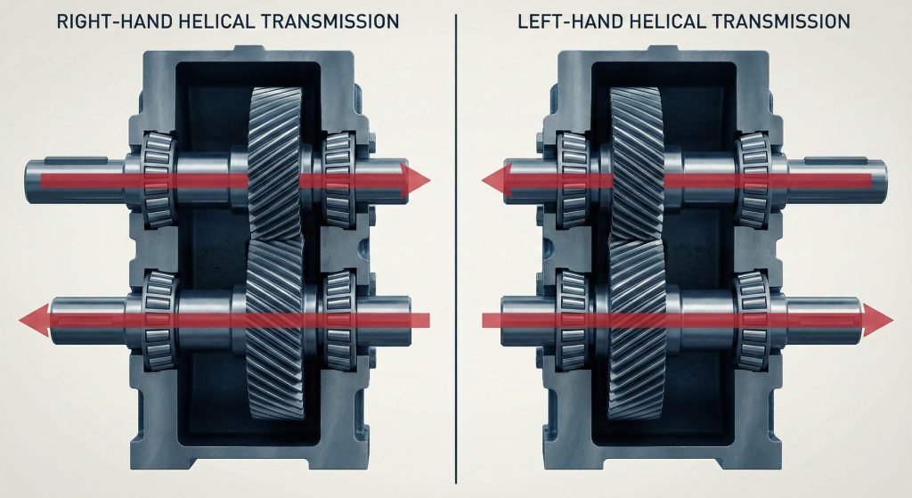
Right-hand or left-hand tooth leaning directly controls helical gear thrust direction regardless of torque levels applied by your drive motors during standard operations. You can identify gear hand by looking at how teeth slope away from your perspective when holding shafts vertically during routine inspection tasks. Parallel shaft arrangements require mating gears with opposite hand orientations to ensure smooth engagement while providing predictable axial thrust paths for bearing selection.
Identifying tooth lean
The secret is:
- Left-hand gears lean toward your left shoulder.
- Right-hand versions tilt toward your right side.
- Orientation determines load vector alignment.
Operational consequences
Look closer:
- Opposite hands work for parallel.
- Same hands work for crossing.
- Reversing hand flips thrust path.
Key Takeaway: Gear hand orientation acts as a primary switch for thrust direction making visual verification a mandatory step for industrial assembly.
| Gear Hand | Parallel Mate | Thrust Direction |
|---|---|---|
| Right | Left | Toward Driver |
| Left | Right | Away Driver |
| Same | Incompatible | Mechanical Jam |
This data confirms that matching gear hands correctly remains a vital prerequisite for any functional power transmission system.
How does load affect helical gear thrust direction?
Increased torque output amplifies helical gear thrust direction magnitude without altering its spatial orientation relative to your rotating shafting or the surrounding gearbox housing. You will find that doubling input power results in twice the axial pressure against thrust washers or tapered roller bearings during heavy production cycles. This linear relationship means high-torque applications generate massive lateral forces that can deflect shafts if left unsupported by engineers.
Torque and force scaling
Wait, there’s more:
- Force grows with input torque.
- Thrust direction remains constant.
- Shock loads cause axial movement.
Managing load spikes
You might wonder:
- Rigid locking prevents gear walking.
- Load magnitude dictates bearing survival.
- Tooth geometry decides force path.
Key Takeaway: Load magnitude dictates how much thrust your bearings must survive but tooth geometry alone decides which way that force points.
| Torque (Nm) | Axial Force (N) | Shaft Deflection |
|---|---|---|
| 100 | 250 | Negligible |
| 500 | 1250 | Measurable |
| 1000 | 2500 | Significant |
High-torque environments necessitate robust axial retention systems to maintain gear mesh integrity under extreme operational stress.
Why is helical gear thrust direction vital for bearings?
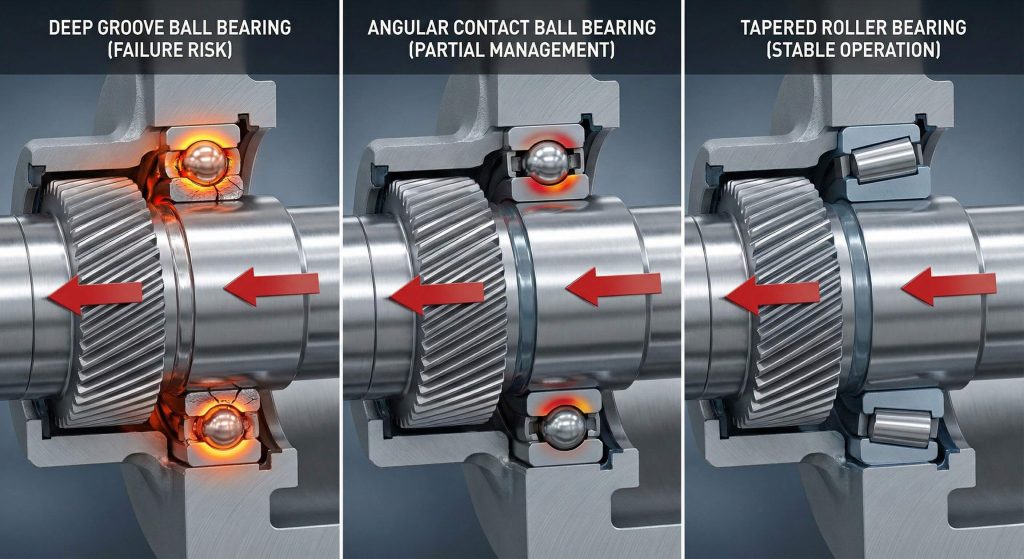
Bearing selection depends entirely on helical gear thrust direction because different types handle axial loads with varying degrees of efficiency and durability in industrial environments. You cannot use standard deep groove ball bearings for high-thrust applications because they lack the necessary contact angles to support sustained sideways pressure. Angular contact or tapered roller bearings remain superior choices as they utilize specialized raceways designed to redirect axial vectors safely.
Supporting axial loads
But here’s the kicker:
- Tapered rollers handle high thrust.
- Ball bearings fail under axial pressure.
- Proper seating prevents shaft drift.
Bearing longevity factors
Think about it:
- Bearing longevity correlates with internal geometry.
- Tapered rollers dominate heavy machinery.
- Seizure ruins entire gear sets.
Key Takeaway: Bearing longevity correlates directly with how well their internal geometry matches the specific thrust vectors produced by helical gear sets.
| Bearing Type | Thrust Capacity | Best Application |
|---|---|---|
| Deep Groove | Low | Light Duty |
| Angular Contact | High | Precision High Speed |
| Tapered Roller | Extreme | Heavy Industrial |
The table above demonstrates why tapered rollers dominate heavy machinery sectors where massive axial thrust remains a constant factor.
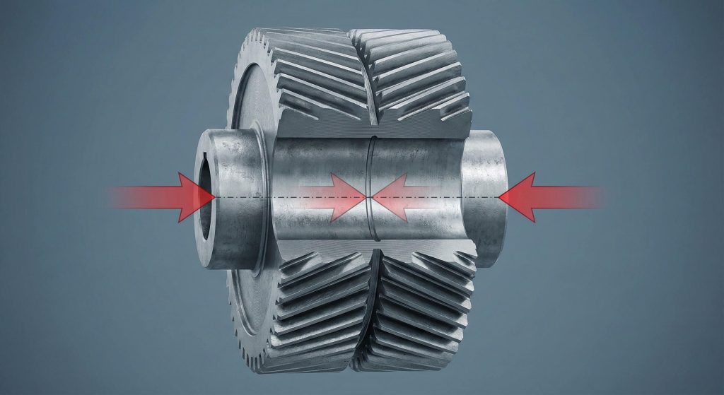
Can double gears nullify helical gear thrust direction?
Double helical or herringbone designs effectively cancel helical gear thrust direction by using two sets of teeth with opposing helix angles on one single gear. You will see that thrust from the left side perfectly counteracts thrust from the right side resulting in zero net axial force during rotation. This balanced approach allows you to transmit enormous torque levels without requiring expensive thrust bearings or heavy-duty housing reinforcements.
Canceling axial forces
The bottom line is:
- Net thrust becomes zero.
- Bearings only handle radial loads.
- Manufacturing costs are much higher.
Structural stability benefits
Ready for the good part?
- Self-balancing nature eliminates complex hardware.
- Zero net thrust simplifies shaft design.
- High-speed turbines require this stability.
Key Takeaway: Double helical gears provide the quietest operation possible while removing the engineering headache of managing massive axial thrust loads.
| Gear Type | Net Thrust | Noise Level | Complexity |
|---|---|---|---|
| Single Helical | High | Low | Moderate |
| Double Helical | Zero | Very Low | High |
| Spur | Zero | High | Low |
Using double helical sets simplifies shaft design significantly because you no longer need to account for lateral movement during high-torque events.
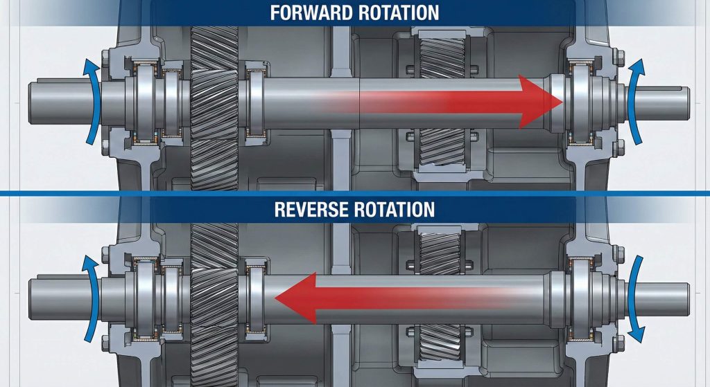
How does rotation shift helical gear thrust direction?
Reversing motor rotation immediately flips helical gear thrust direction to the opposite side of your gearbox housing during routine operational cycles. You must design your system with bidirectional thrust support if your application requires frequent changes in drive direction for specific task completion. Single-direction thrust bearings will fail catastrophically if the shaft begins pushing in the unintended direction because they cannot provide any resistance to that vector.
Directional force reversal
The secret is:
- Clockwise rotation pushes one way.
- Counter-clockwise pushes the other.
- Bidirectional needs double support.
Managing force shifts
Think about it:
- Flipping rotation reverses the sliding vector.
- Back-to-back bearings capture both paths.
- Tight shims prevent axial hammering.
Key Takeaway: Rotation direction acts as a secondary control for thrust path meaning you must anticipate force reversals in any reversible drive system.
| Rotation | Helix Hand | Thrust Path |
|---|---|---|
| Forward | Right | Toward Outboard |
| Reverse | Right | Toward Inboard |
| Forward | Left | Toward Inboard |
Predicting these shifts allows for the installation of appropriate shims to maintain perfect gear alignment even when motor polarity changes.
What math predicts helical gear thrust direction force?
Calculations for helical gear thrust direction magnitude utilize the tangent of the helix angle multiplied by the tangential driving force during the design phase. You can use the formula Fa = Ft * tan(beta) to find the exact axial load in Newtons for your engineering projects today. Tangential force derives from motor torque and gear pitch diameter so accurate measurements are required for precise results.
Calculating axial vectors
Ready for the good part?
- Tangent math is very accurate.
- Pitch diameter influences force.
- Safety factors protect your bearings.
Predictive modeling benefits
It gets better:
- Mastery of formulas ensures reliability.
- Accurate measurements prevent field failure.
- Trigonometric relationships define tooth tilt.
Key Takeaway: Precise mathematical modeling is the only way to guarantee that your gearbox can survive the axial loads generated by helical gears.
| Variable | Definition | Unit |
|---|---|---|
| Fa | Axial Force | Newtons |
| Ft | Tangential Force | Newtons |
| Beta | Helix Angle | Degrees |
Applying these formulas during the design stage prevents expensive field failures and reduces the risk of unexpected maintenance costs.
Does pitch influence helical gear thrust direction?
Fine pitch gears distribute helical gear thrust direction across more teeth which can reduce localized stress on individual contact points during heavy operation. You will find that coarser pitches concentrate forces on fewer teeth which might lead to higher wear rates if lubrication is inadequate. While pitch does not change the overall magnitude of the thrust vector, it significantly impacts how that force is transmitted through the gear mesh.
Pitch and load distribution
Think about it:
- Fine pitch is quieter.
- Coarse pitch is stronger.
- More teeth share the load.
Optimization strategies
You might wonder:
- More teeth in contact reduces pressure.
- Oil film thickness mitigates sliding friction.
- Pitch selection balances torque and noise.
Key Takeaway: Pitch selection modifies how axial forces are shared across the gear face even if the total thrust remains the same.
| Pitch Type | Teeth in Mesh | Noise Level | Load Strength |
|---|---|---|---|
| Fine | 3-4 | Very Low | Moderate |
| Medium | 2-3 | Low | High |
| Coarse | 1-2 | Moderate | Very High |
Using this data helps you select the best tooth size for your specific torque and noise requirements without compromising on mechanical reliability.
How to manage helical gear thrust direction in housings?
Rigid housing designs must absorb helical gear thrust direction forces without experiencing significant flexing or misalignment of internal shafting during heavy load cycles. You should use cast iron or steel housings for high-thrust applications because aluminum might deform under the constant lateral pressure of the rotating gears. Internal ribs and thickened walls near bearing seats help distribute axial loads into the machine base more effectively.
Housing rigidity factors
The bottom line is:
- Rigid housings prevent twisting.
- Cast iron is best for thrust.
- Shimming sets proper end-play.
Structural integrity analysis
Ready for the good part?
- Bracing prevent gearbox twisting.
- Structural integrity is a hallmark of quality.
- Cast iron offers superior thermal stability.
Key Takeaway: The best gear design will fail if the housing cannot support the axial thrust forces generated during high-torque operation.
| Material | Rigidity | Thermal Stability | Weight |
|---|---|---|---|
| Cast Iron | Excellent | High | Heavy |
| Aluminum | Moderate | Medium | Light |
| Steel Alloy | Superior | High | Moderate |
Proper housing selection ensures that your internal components stay perfectly aligned even when subjected to extreme axial forces during production.
Frequently Asked Questions
Can I ignore axial thrust if the helix angle is very small?
No, this is a critical oversight. Even small angles generate significant lateral forces that will eventually destroy standard radial bearings during continuous operation cycles in industrial settings.
What’s the best bearing for high-speed helical gear thrust?
Angular contact ball bearings are definitely the superior choice. They handle both radial and axial loads with very low friction at high speeds compared to other bearing designs.
How do I know if my axial thrust is too high?
Your equipment will show clear warning signs. Excessive heat near bearing seats or visible metal shavings in the lubrication oil often indicate that thrust loads are exceeding bearing capacities.
Can I use thrust washers instead of bearings?
This is only viable for light duty applications. Thrust washers work for low-speed applications but they generate too much heat for high-speed industrial power transmission systems requiring longevity.
What’s the best way to reverse helical gear thrust?
You must change the physical path of the force. You can reverse the thrust path by either changing the rotation direction or by swapping for a gear with the opposite hand.
Conclusion
Mastering axial vectors ensures mechanical longevity and operational safety across all your industrial applications. Proper bearing selection mitigates risks while enhancing system reliability for your business. Do you require custom engineering assistance for your next project? Our specialists provide high-precision components for any application so contact us today for a consultation.