Introduction
Designing mechanical power transmission systems often feels like navigating a minefield of potential failures where one wrong number creates a disaster. One miscalculation in your geometry leads to deafening noise, rapid wear, or catastrophic breakage that halts production lines instantly. Here’s the deal: you need a reliable method to verify every dimension before cutting a single chip. Our solution provides the definitive spur gear calculation example framework to guarantee your components mesh perfectly every time.
What is a spur gear calculation example for basic geometry?
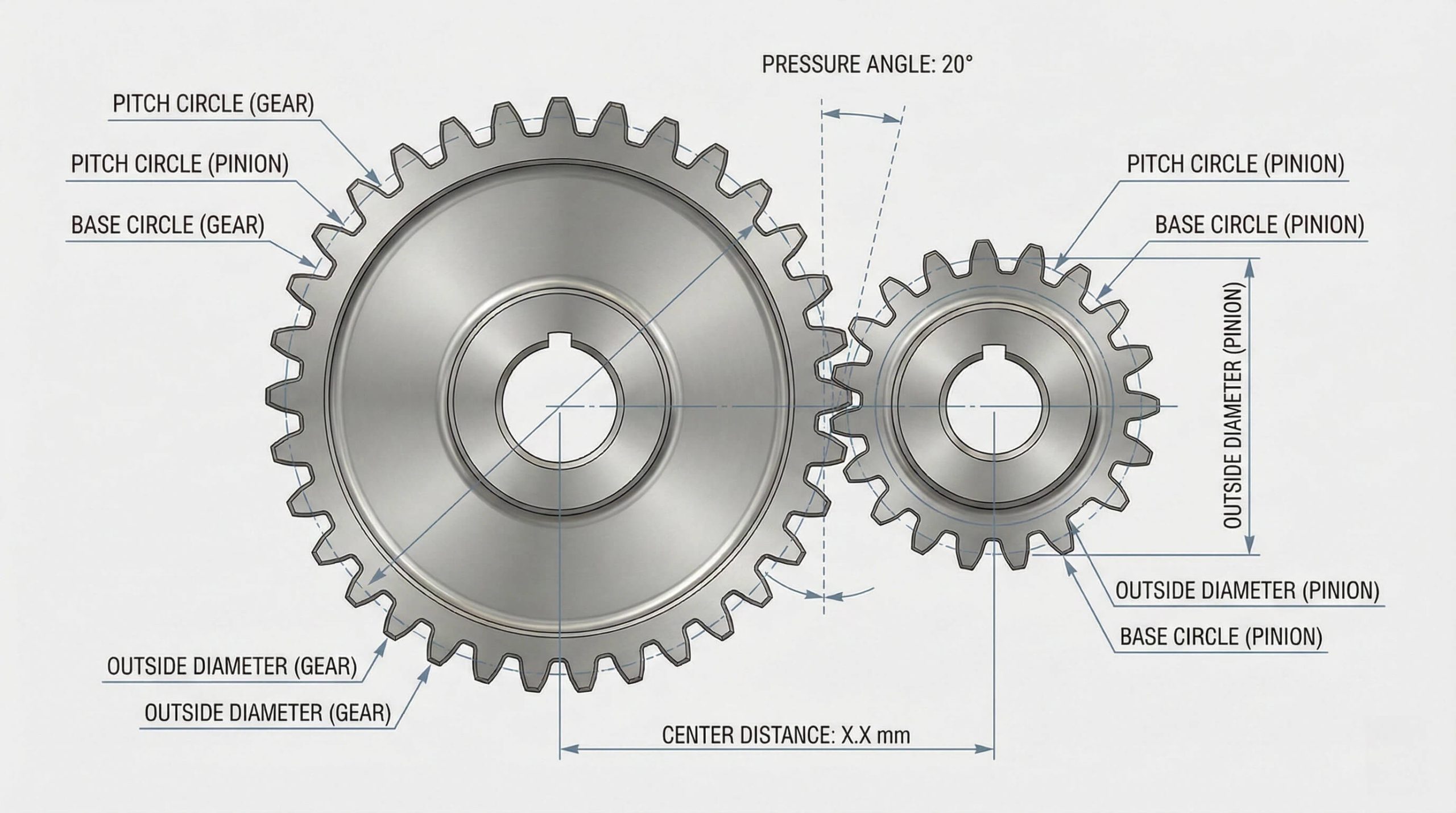
Standard equations defining spur gear geometry form the mathematical backbone of any mechanical system fit and function. A proper spur gear calculation example must identify variables like Pressure Angle ($\phi$) and Number of Teeth ($N$) immediately. Without these values, you cannot use our Gear Dimensions Calculator to find critical dimensions. You might be wondering why symbols matter so much in this process.
Identifying Standard Variables
Now that you see the variables, applying them requires precision. Confusing symbols remains the primary cause for costly manufacturing errors in engineering shops. You must define Pressure Angle ($\phi$) and Pitch Diameter ($D$) before attempting complex math. But here’s the kicker: inconsistent units will ruin your design. Always verify your constants match your measurement system.
- $\phi$ (Phi): Pressure Angle.
- $D$: Pitch Diameter.
- $N$: Number of Teeth.
- $P$: Diametral Pitch.
Calculating Base Dimensions
Key Takeaway: Accurate mapping of symbols to physical constraints prevents fundamental design errors.
| Variable | Symbol | Basic Formula Relationship |
|---|---|---|
| Base Circle Diameter | $D_B$ | $D_B = D \cos \phi$ |
| Pitch Diameter | $D$ | $D = N / P$ |
| Number of Teeth | $N$ | $N = P \times D$ |
Analysis: Understanding these base definitions ensures you can derive any missing variable from the other two.
How does a spur gear calculation example determine center distance?
Center Distance ($C$) represents the precise average of the pitch diameters for two meshing gears. A robust spur gear calculation example uses this dimension to dictate shaft spacing and drive efficiency. Spur Gear Design Calculator tools often automate this process, but understanding the math ensures you can verify the results.
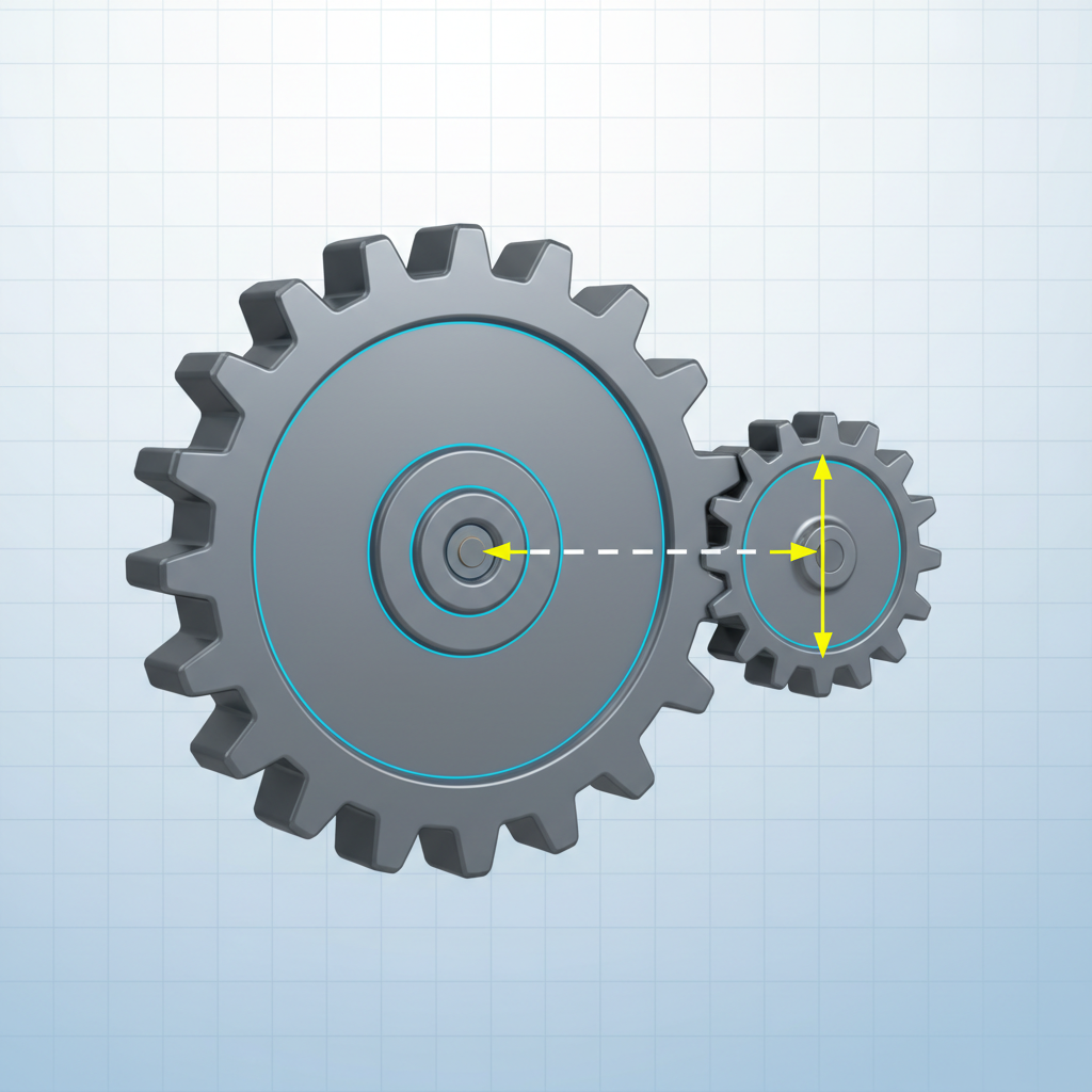
Using Pitch Diameters
You might not know that center distance dictates the entire housing design. Getting this wrong causes gears to bind or fail to contact. So, calculating this value early saves significant rework time later.
- Calculate Pinion Pitch Diameter ($D_P$).
- Calculate Gear Pitch Diameter ($D_G$).
- Sum these values and divide by two.
Finalizing Assembly Spacing
But wait, checking tooth counts offers another verification method.
Key Takeaway: Correct Center Distance calculation prevents premature wear and ensures smooth power transmission.
| Method | Formula | Application |
|---|---|---|
| Diameter Based | $C = (D_P + D_G) / 2$ | Used when physical sizes are known. |
| Tooth Count Based | $C = (N_G + N_P) / 2P$ | Used during initial design phase. |
| Circular Pitch Based | $C = (N_G + N_P) p / 6.2832$ | Used when working with circular pitch. |
Analysis: Tooth-count formulas generally provide better accuracy during early design stages by using integers.
Why is diametral pitch crucial in a spur gear calculation example?
Diametral Pitch ($P$) defines tooth size relative to gear diameter, acting as the system’s heartbeat. Any practical spur gear calculation example requires $P$ to be an integer for standard tooling compatibility. Think about it: mismatched pitches simply will not mesh.
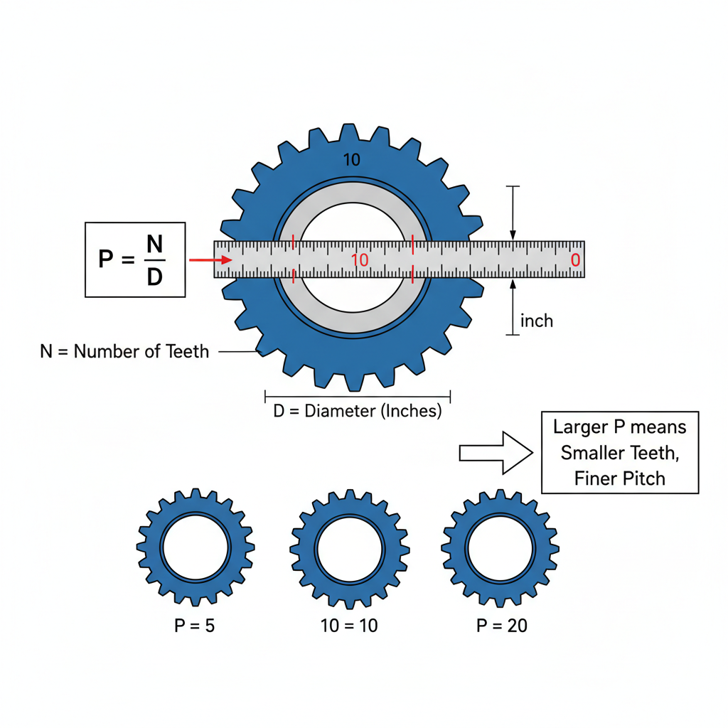
Relationship to Circular Pitch
Here’s the catch: Diametral Pitch shares an inverse relationship with physical tooth size. Higher $P$ values indicate smaller teeth, while lower numbers mean robust, large teeth. You must select this value carefully.
- $P$ and Circular Pitch ($p$) relate via $\pi$.
- $P = \pi / p$.
- Knowing one value instantly provides the other.
Converting Standards
What’s the real story? You need standard integers to reduce tooling costs.
Key Takeaway: Establishing Diametral Pitch early governs all other tooth dimensions.
| To Find | Formula | Context |
|---|---|---|
| Diametral Pitch ($P$) | $P = \pi / p$ | Converting from Circular Pitch. |
| Diametral Pitch ($P$) | $P = N / D$ | Standard definition. |
| Diametral Pitch ($P$) | $P = [N p (m_G + 1)] / 2C$ | Advanced system calculation. |
Analysis: Selecting a standard integer pitch like 4 or 10 significantly lowers manufacturing difficulty.
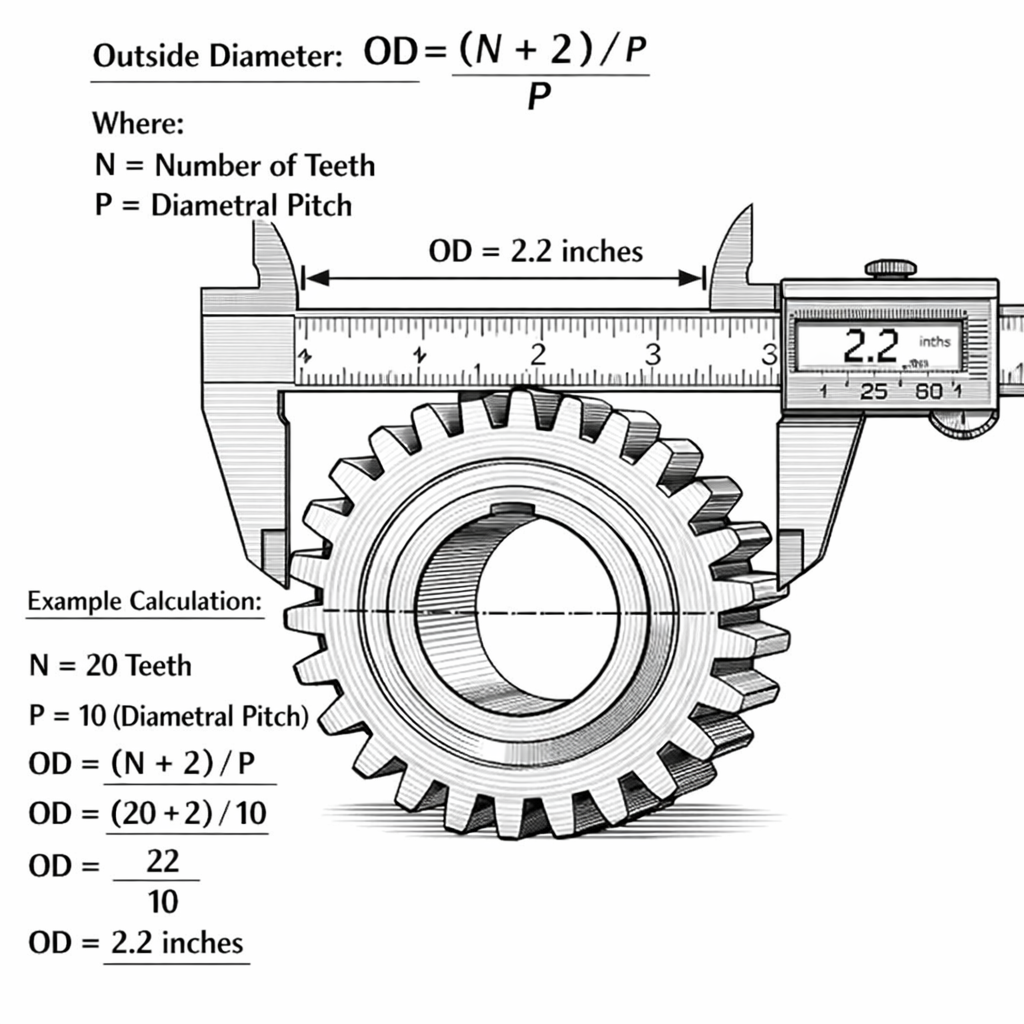
How do you find outside diameter in a spur gear calculation example?
Outside Diameter ($D_O$) measures the overall size across the gear tips before or after cutting. A comprehensive spur gear calculation example calculates this to ensure fitment within a housing. Ideally, you check this dimension first to verify stock material availability.
Full Depth Teeth Formulas
But here’s the kicker: Formulas change depending on whether you use Full Depth or Stub teeth. You must know which standard applies to your specific project. Mixing these standards causes immediate interference.
- Add 2 to Number of Teeth ($N$).
- Divide this sum by Diametral Pitch ($P$).
- This result gives standard Full Depth OD.
Verifying Blank Sizes
You might be wondering if stub teeth differ significantly.
Key Takeaway: Outside Diameter serves as your primary manufacturing check dimension.
| Tooth Form | Formula | Description |
|---|---|---|
| Full Depth | $D_O = (N + 2) / P$ | Standard industrial profile. |
| Stub Tooth | $D_O = (N + 1.6) / P$ | Heavy-duty, shorter profile. |
| Circular Pitch | $D_O = (N + 2)p / \pi$ | Calculation using $p$. |
Analysis: Stub teeth provide higher strength but result in a slightly smaller outside diameter.
When should a spur gear calculation example use circular pitch?
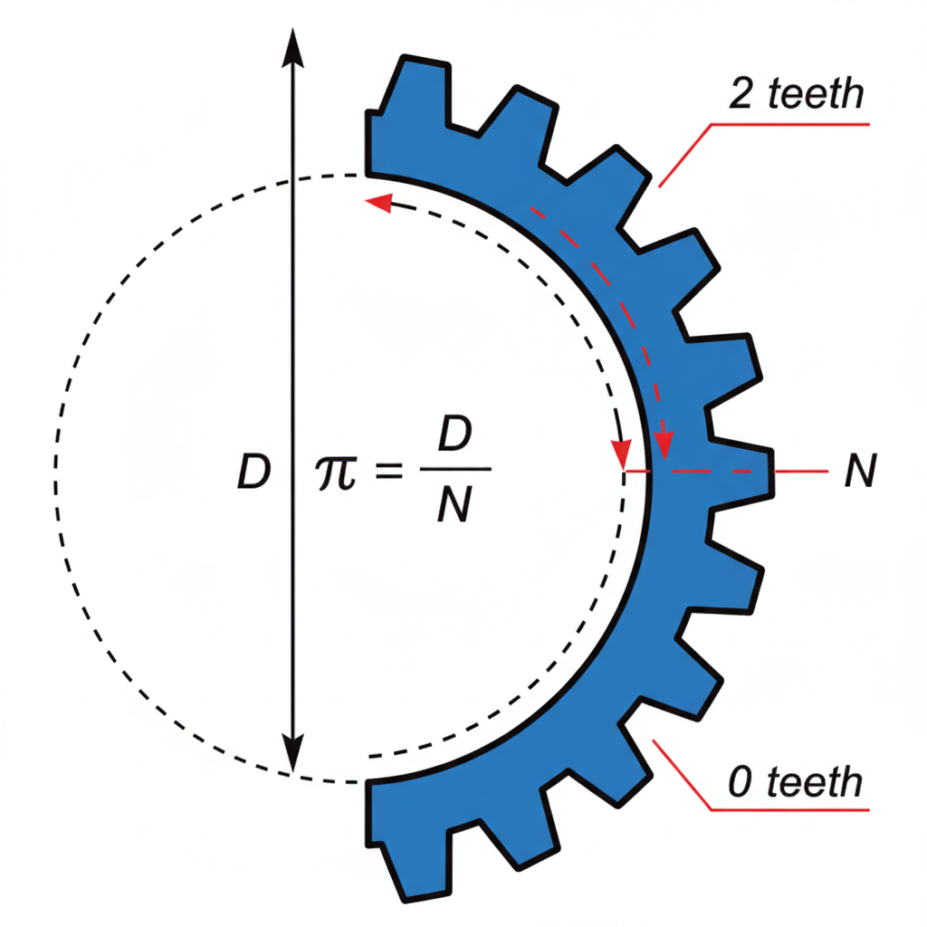
Circular Pitch ($p$) measures the actual distance along the pitch circle between adjacent teeth. You typically use a spur gear calculation example involving $p$ for large cast gears or legacy machinery. It makes sense that older designs favor this direct measurement method.
Calculating from Diameter
Here’s the thing: Circular pitch formulas include the irrational number $\pi$. This makes precise calculation slightly more cumbersome than using Diametral Pitch. Precision demands careful handling of decimal places.
- Multiply Pitch Diameter ($D$) by $\pi$.
- Divide result by Number of Teeth ($N$).
- This yields arc length between teeth.
Metric vs Imperial Contexts
Ready for the good part? Knowing both methods makes you a versatile engineer.
Key Takeaway: Circular Pitch is essential for understanding physical arc distance between teeth.
| Variable | Formula | Notes |
|---|---|---|
| Circular Pitch ($p$) | $p = (\pi D) / N$ | Definition based on geometry. |
| Circular Pitch ($p$) | $p = \pi / P$ | Conversion from Diametral Pitch. |
| Tooth Thickness | $t = p / 2$ | Basic thickness is half pitch. |
Analysis: Using Circular Pitch ($p$) becomes necessary when reverse-engineering older gears lacking integer pitches.
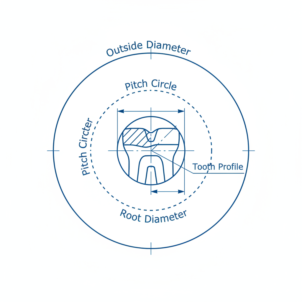
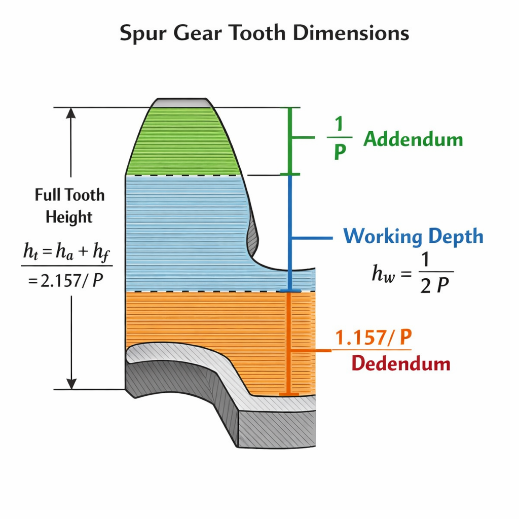
What spur gear calculation example defines tooth parts?
Machining a gear requires knowing the exact depth and height for every tooth. A detailed spur gear calculation example defines Addendum ($a$) and Dedendum ($b$) precisely. Basic Gear Terminology often defines these parts relative to the pitch circle.
Calculating Addendum and Dedendum
You might be surprised that clearance is derived specifically to allow lubrication. Basically, tooth depth must be accurate to within thousandths of an inch. Errors here cause binding or excessive heat.
- Addendum ($a$): $1.000 / P$.
- Dedendum ($b$): $1.250 / P$.
- Result: Standard tooth profile.
Handling Pressure Angles
But wait, you must also account for working depth.
Key Takeaway: The relationship between Addendum and Dedendum provides necessary clearance for operation.
| Feature | Formula (Preferred) | Formula (Circular Pitch) |
|---|---|---|
| Addendum ($a$) | $1.000 / P$ | $0.3183 \times p$ |
| Dedendum ($b$) | $1.250 / P$ | $0.3979 \times p$ |
| Whole Depth ($h_t$) | $2.250 / P$ | $0.7162 \times p$ |
Analysis: Whole depth ($h_t$) represents the total cut depth required by machine operators.
How does a spur gear calculation example adjust for shaved teeth?
High-precision gears often require shaving or grinding after the initial cut. A sophisticated spur gear calculation example accounts for this by deepening the root. What’s the catch? Standard formulas cause interference if you ignore the finishing tool.
Adjusting Dedendum for Shaving
Here’s the deal: Shaved gears need a deeper root ($b$) to accommodate the tool tip. You must increase depth to avoid creating stress risers.
- Standard Dedendum: $1.250 / P$.
- Shaved Dedendum: $1.350 / P$.
- Extra depth allows for cutter fillet.
Preventing Stress Concentrations
Now that you see the difference, always check your process.
Key Takeaway: Failing to deepen roots for shaved gears leads to dangerous stress concentrations.
| Process | Feature | Adjusted Formula |
|---|---|---|
| Shaved/Ground | Dedendum ($b$) | $1.350 / P$ |
| Shaved/Ground | Whole Depth ($h_t$) | $2.350 / P$ |
| Shaved/Ground | Clearance ($c$) | $0.350 / P$ |
Analysis: Always specify manufacturing processes before calculating final tooth depths.
How does a spur gear calculation example utilize the circular pitch table?
Sometimes looking up standard data is faster than calculating it. A spur gear calculation example often references a Circular Pitches and Equivalent Diametral Pitches Table for quick sizing. This resource links Diametral Pitch, Circular Pitch, and Module together.
Reading the Equivalent Pitches
You can imagine the time saved versus calculating $\pi$ repeatedly. You simply locate the row matching your desired pitch. Most engineers rely on these tables daily.
- Find Diametral Pitch (e.g., 4).
- Read across to Circular Pitch (0.7854).
- Verify Arc Thickness (0.3927).
Selecting Standard Sizes
But here’s the kicker: Use tables to verify metric compatibility.
Key Takeaway: Using standard values ensures gears match off-the-shelf cutters.
| Diametral Pitch ($P$) | Circular Pitch ($p$) | Module | Addendum |
|---|---|---|---|
| 1 | 3.1416 | 25.40 | 1.0000 |
| 2 | 1.5708 | 12.70 | 0.5000 |
| 4 | 0.7854 | 6.35 | 0.2500 |
Analysis: The table reveals that doubling Diametral Pitch exactly halves physical dimensions.
How does the gear ratio impact a spur gear calculation example?
Gear Ratio ($m_G$) defines the speed and torque modification for your mechanical system. In a dynamic spur gear calculation example, this ratio determines relative sizes for driver and driven gears. Basically, it tells you how many pinion turns equal one gear turn.
Defining Ratio from Teeth
Here’s the thing: Gear ratio also dictates center distance constraints. Gear Ratio Calculator tools become essential for balancing these competing variables.
- Divide Teeth in Gear ($N_G$) by Teeth in Pinion ($N_P$).
- $m_G = N_G / N_P$.
- Ratios $>1$ reduce speed; $<1$ increase it.
Optimizing Speed Reduction
Ready for the good part? You can reverse this to find tooth counts.
Key Takeaway: Gear Ratio is the functional goal; pitch and diameter are merely physical means.
| Variable | Formula | Purpose |
|---|---|---|
| Gear Ratio ($m_G$) | $m_G = N_G / N_P$ | Calculate mechanical advantage. |
| Pinion Teeth ($N_P$) | $N_P = (2 C P) / (m_G + 1)$ | Solve for pinion size. |
| Gear Teeth ($N_G$) | $N_G = m_G \times N_P$ | Solve for gear size. |
Analysis: The formula $N_P = (2 C P) / (m_G + 1)$ fits a specific ratio into fixed housings.
What spur gear calculation example applies to stub teeth?
Stub teeth offer a modified form where strength overrides smooth operation requirements. A spur gear calculation example for stub teeth uses different constants than standard full-depth forms. You might need this for heavy machinery or automotive transmissions.
American Standard Stub Formulas
Here’s the deal: Stub teeth feature shorter addendums ($0.8/P$) compared to standard ones. This makes them thicker at the base and stronger.
- Addendum: $0.800 / P$.
- Dedendum: $1.000 / P$.
- Working Depth: $1.600 / P$.
Calculating Stub Dimensions
But wait, shorter teeth mean less contact ratio.
Key Takeaway: Stub tooth calculations simply replace standard constants with stub constants.
| Feature | Stub Formula | Standard Formula |
|---|---|---|
| Addendum ($a$) | $0.800 / P$ | $1.000 / P$ |
| Whole Depth ($h_t$) | $1.800 / P$ | $2.250 / P$ |
| Outside Diameter | $(N + 1.6) / P$ | $(N + 2) / P$ |
Analysis: Stub profiles result in physically smaller diameters for equal tooth counts.
Conclusion
Designing reliable spur gears demands more than guesswork; it requires precise application of standard equations. By following a structured spur gear calculation example, from determining Diametral Pitch to consulting the Circular Pitch table, you ensure components mesh correctly. Whether calculating for a prototype or industrial drive, these formulas serve as your blueprint.
Ready to optimize? Don’t let calculation errors stall your production. Contact us at GearAide today to discuss your custom gear needs. We combine precision engineering with practical expertise to solve tough transmission problems.
FAQ
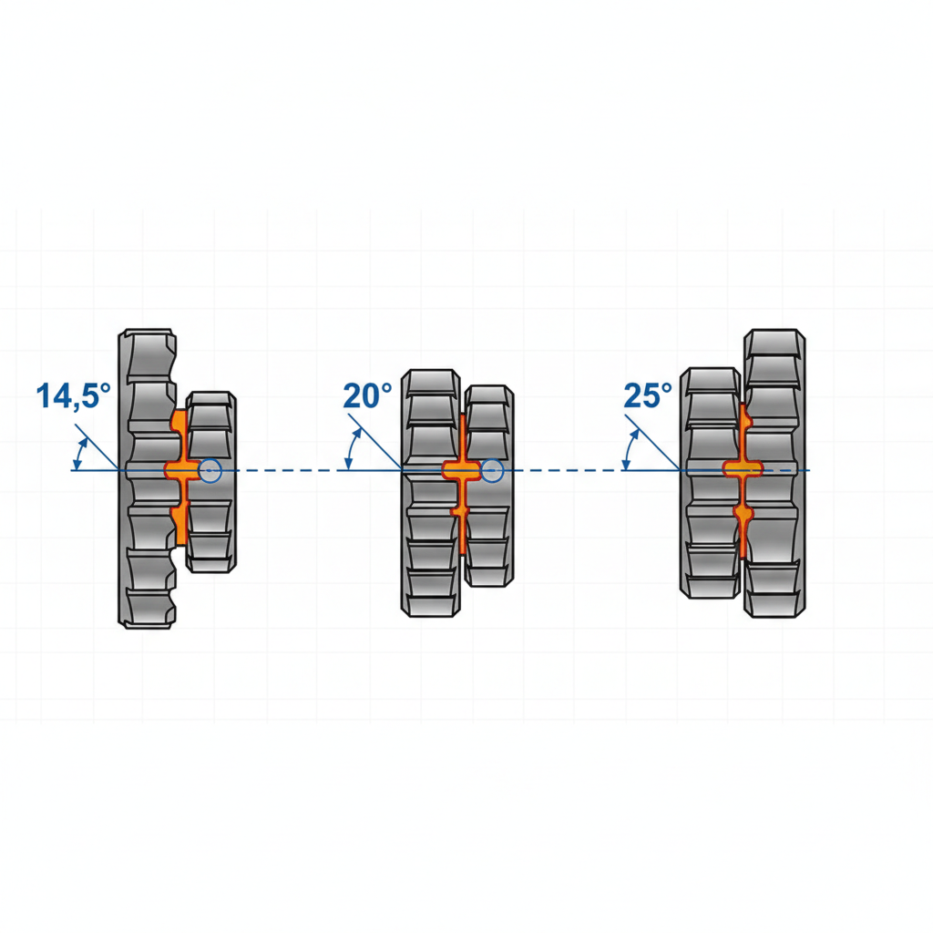
Can I mix 20-degree and 25-degree pressure angle gears?
No, mixing pressure angles causes immediate interference because the tooth profiles will not roll smoothly against each other. This misalignment leads to excessive noise, rapid heat generation, and eventual destruction of the gear teeth.
What is the best way to determine the correct module for my gear?
You should determine the module by dividing the pitch diameter in millimeters by the number of teeth. This metric offers a precise measure of tooth size that aligns with international standards for gear manufacturing.
How do I know if I need to use shaved tooth calculations?
You need shaved tooth calculations if your application requires high precision or low noise, as this process removes a small amount of material from the tooth face. Standard formulas will not account for the deeper root required for the shaving tool clearance.