The design shapes of spur gears are defined by specific geometric parameters like the module, pressure angle, and tooth profile that determine how gears transmit motion and power. Understanding these shapes is the primary solution to ensuring your machinery runs with quiet, unbreakable reliability. You must master the geometry and specifications to design a spur gear to avoid the hidden design flaws that lead to costly mechanical failure. These principles provide the technical foresight needed to maximize the lifespan of mechanical drives in industrial environments.
Why is the module system vital to design a spur gear?
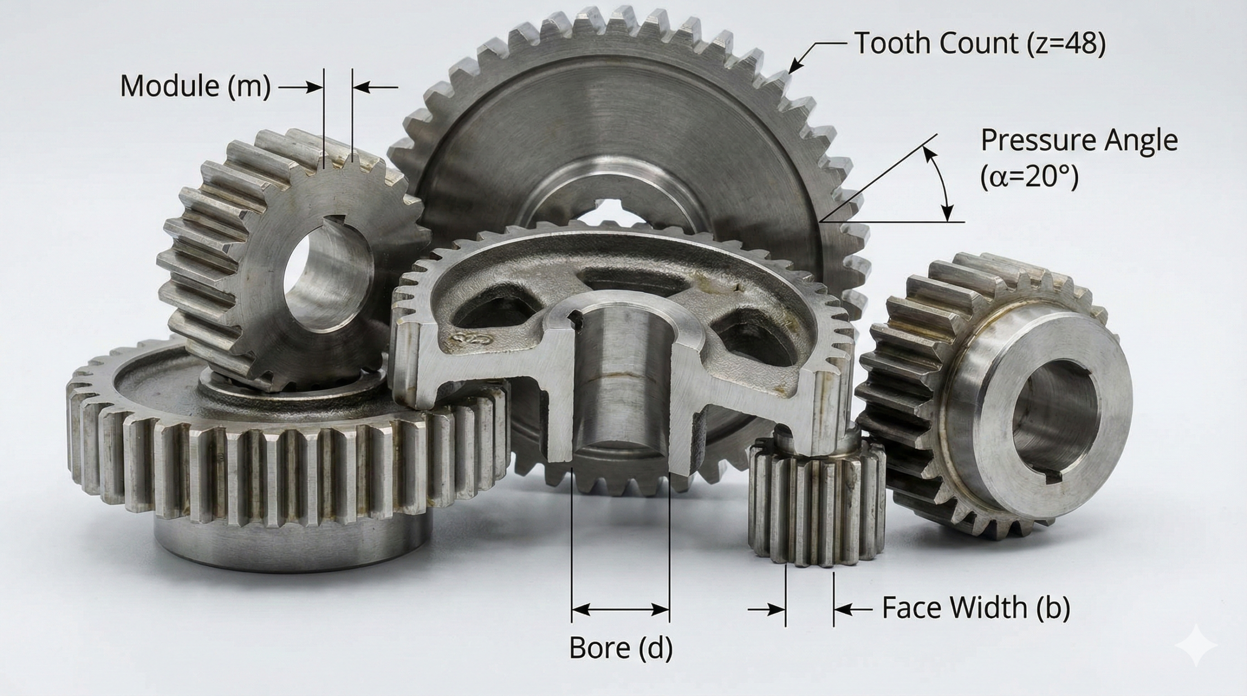
The module system is vital because it establishes the fundamental scale and tooth size for your entire power transmission system. When you design a spur gear, you must realize that the module represents the ratio of the pitch diameter to the number of teeth. This single value dictates the strength of the gear teeth and their ability to mesh with other components.
How does module choice affect sizing?
The module determines the physical height and thickness of each gear tooth in the set. You will find that larger modules provide the robust structural integrity required for heavy-duty industrial lifting equipment. Smaller modules conversely allow for the creation of compact, high-speed mechanisms used in precision robotics.
Standardizing your dimensions
Using standard metric modules simplifies your procurement process and reduces manufacturing costs significantly. You should stick to recognized series to ensure that replacement parts are readily available from global suppliers. Non-standard sizes might offer minor specialized benefits but often result in long lead times.
Key Takeaway: The module acts as the geometric foundation that ensures compatibility and tooth strength across all mating components.
| Parameter | Calculation | Result |
|---|---|---|
| Pitch Diameter | Module × Teeth | Effective Size |
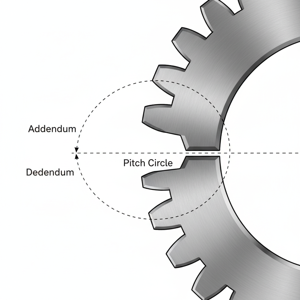
| Addendum | 1.0 × Module | Tooth Height |
Analytical Guide: Standardizing the module eliminates custom tooling costs while ensuring predictable stress distribution across each functional tooth flank.
How many teeth should you use to design a spur gear?
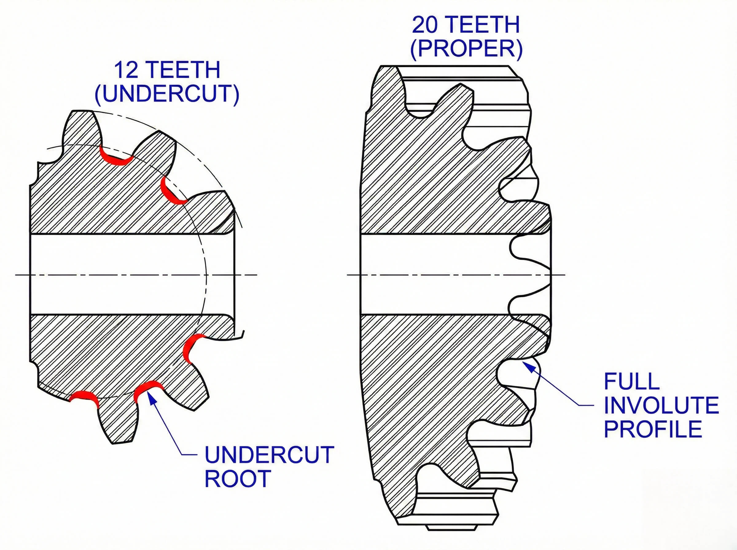
You should select a tooth count that satisfies your required speed ratio while maintaining a minimum of seventeen teeth to prevent manufacturing interference. Choosing the optimal tooth count is the primary method for defining the speed and torque ratios of your mechanical drive. To design a gear correctly, you must balance the desired output speed against the physical constraints of the gear housing.
Avoiding the trap of undercutting
If you specify a pinion with fewer than seventeen teeth, you risk undercutting the tooth roots during manufacturing. Undercutting occurs when the cutting tool removes material from the base of the tooth during the generation process. This removal of material weakens the tooth significantly and can lead to sudden fatigue failure under load.
Why does contact ratio matter?
You should aim for a higher tooth count when your application demands smooth and quiet operation at high speeds. A higher number of teeth typically increases the contact ratio, meaning more than one tooth pair is engaged simultaneously. This distribution of force reduces the impact stress on individual teeth and minimizes acoustic resonance.
Key Takeaway: Balancing tooth count prevents premature mechanical failure and optimizes the smoothness of motion transfer.
| Ratio Requirement | Typical Pinion Teeth | Typical Gear Teeth |
|---|---|---|
| 2:1 Reduction | 20 Teeth | 40 Teeth |
| 4:1 Reduction | 18 Teeth | 72 Teeth |
Analytical Guide: Proper tooth count selection represents a compromise between desired torque multiplication and geometric limits inherent to involute curves.
What hub styles do you need to design a spur gear?
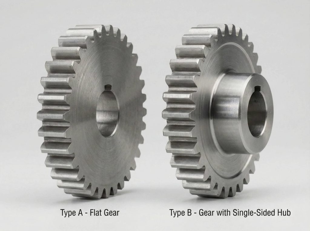
You need hub styles that match your available axial space and mounting requirements, typically choosing between flat plates or protruding single-sided hubs. When you design a spur gear, you must choose the configuration that ensures the gear remains securely mounted on its driving shaft. The hub style also influences the weight and rotational inertia of the entire assembly.
Selecting between Type A and B hubs
Type A gears are simple flat discs that work best when you have extremely limited axial space within a housing. Type B gears feature a protruding hub on one side, which provides more surface area for a robust keyway attachment. You will find that Type B is the industry standard for most general-purpose mechanical transmissions.
Can hub geometry reduce weight?
You might want to consider webbed or spoked hubs for gears with large pitch diameters to save material and reduce costs. By removing material between the rim and the central hub, you can significantly reduce the rotational inertia of the system. This allows your machinery to accelerate and decelerate more rapidly without overworking the motor.
Key Takeaway: Hub selection is governed by available axial space and the preferred method of shaft attachment for torque transfer.
| Hub Style | Mounting Space | Weight Profile |
|---|---|---|
| Type A (Plain) | Minimal | Low |
| Type B (Hubbed) | Moderate | Medium |
Analytical Guide: Selecting the appropriate hub geometry remains essential for managing tradeoffs between component weight and mechanical strength.
Does pressure angle change how you design a spur gear?
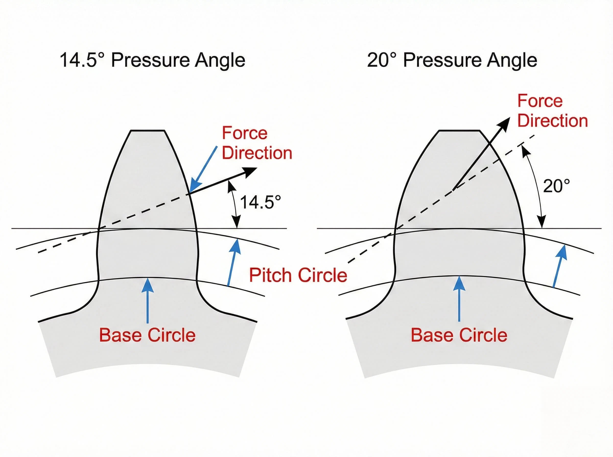
Pressure angle changes the tooth strength and the radial force acting on your bearings, with a 20-degree angle providing a thicker, stronger tooth base. The pressure angle dictates the direction of the force transmitted between mating teeth and influences the load capacity of the set. To design for modern industrial use, you will almost always select the 20-degree standard.
Comparing 14.5 and 20-degree profiles
A 20-degree pressure angle creates a wider tooth base that resists bending far better than the older 14.5-degree standard. While the 14.5-degree profile was once common for its quiet operation, it is now largely reserved for legacy machinery. You should adopt the 20-degree profile to maximize the power density of your new designs.
How do force vectors change?
You must account for the fact that higher pressure angles increase the radial loads acting on your shaft bearings. As the angle increases, more of the transmitted force tries to push the gears apart rather than just rotating them. You need to ensure your housing and bearings are robust enough to handle these increased separation forces.
Key Takeaway: Use 20° for power transmission and 14.5° only for legacy replacements or specialized smooth-motion needs.
| Pressure Angle | Tooth Strength | Bearing Stress |
|---|---|---|
| 14.5° | Lower | Low |
| 20.0° | Higher | Moderate |
Analytical Guide: The choice of pressure angle directly influences sliding velocity while impacting both thermal efficiency and wear rates.
Which bore standards apply when you design a spur gear?
Bore standards involve specifying precise diameter tolerances, such as H7, to ensure a stable fit and prevent destructive shaft vibration. If you design a spur gear without considering the shaft fit, you risk causing uneven tooth wear and premature bearing failure. Precision bore finishing is the secret to a balanced system that runs smoothly for years.
The importance of fit tolerances
A few microns of clearance can make the difference between a perfect fit and a wobbling assembly during high-speed rotation. You should typically specify an H7 tolerance for the bore to achieve a high-precision slip fit that is easy to assemble. If your application involves extreme shocks, a transition or interference fit may be necessary to prevent shifting.
Should you use a keyway or spline?
For standard industrial torque, a single keyway is usually sufficient and cost-effective for most power transmission needs. However, if you are designing for heavy-duty cycling or reversing loads, you might need a splined bore to distribute torque. This prevents the key from shearing and protects the integrity of the shaft-to-gear interface.
Key Takeaway: Precision in bore finishing is the difference between a balanced system and one that suffers from destructive vibration.
| Fit Type | Tolerance Class | Application |
|---|---|---|
| Clearance | H7/h6 | General Assembly |
| Interference | P7/h6 | High Shock Loads |
Analytical Guide: Properly specified bore tolerances prevent eccentricity which acts as the primary cause for uneven tooth wear.
How do you manage backlash as you design a spur gear?
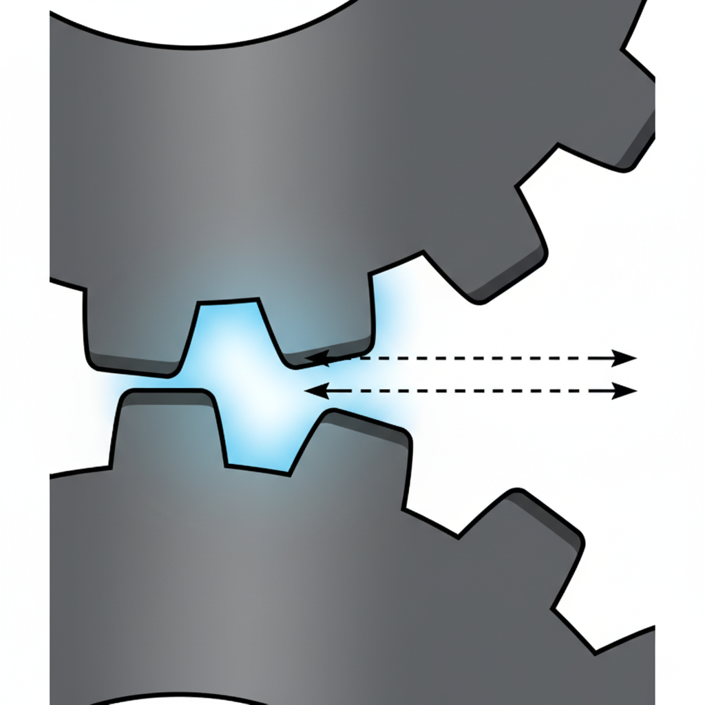
You manage backlash by providing an intentional gap between mating teeth to allow for lubrication flow and thermal expansion during operation. Backlash is essential to prevent mechanical jamming when the gears heat up under load. For most power transmission tasks, a standard backlash amount ensures a cooler running temperature and longer service life.
Maintaining the ideal clearance
In standard industrial drives, zero backlash causes excessive friction, localized heating, and rapid wear of the tooth flanks. You should only pursue near-zero backlash in precision positioning systems where directional accuracy is paramount. You must check the manufacturer’s recommendations for your specific center distance to maintain the ideal clearance.
Why is thermal expansion a risk?
As gears rotate under load, they generate heat that causes the metal to expand slightly in all directions. If you do not design sufficient backlash into the set, the teeth will eventually bind against each other as they grow. This leads to a catastrophic seizure that can destroy the entire gearbox and internal components.
Key Takeaway: Some backlash is mandatory for mechanical health; zero backlash requires specialized pre-loaded components.
| Backlash Amount | Operating Speed | Noise Level |
|---|---|---|
| Minimal | Low | Very Quiet |
| Normal | High | Standard |
Analytical Guide: Controlling backlash involves a delicate balance between preventing jamming and maintaining the fidelity of the motion profile.
Is web thickness important when you design a spur gear?
Web thickness is vital because it connects the rim to the hub and provides the rigidity needed to prevent tooth misalignment under load. To design a spur gear that can withstand heavy vibrations, you must ensure the web is thick enough to resist deflection. If the web is too thin, axial deflection can lead to catastrophic edge loading on the teeth.
Stiffening the gear body
Making the web too thick adds unnecessary weight and rotational inertia to your system which reduces overall energy efficiency. You can optimize your design by adding radial stiffening ribs to a thinner web to increase strength without weight. This approach is particularly effective for large-diameter gears used in industrial mixers or heavy conveyors.
How do lightning holes help?
You should consider adding lightning holes in the web area to further reduce mass if the gear rotates at high speeds. These holes allow you to balance the gear more effectively and reduce the load on your motor during startup. Ensure that the remaining material still provides a solid path for the torque to flow from the teeth to the shaft.
Key Takeaway: A well-designed web provides maximum stiffness with minimum rotational mass for the drive system.
| Web Feature | Benefit | Drawback |
|---|---|---|
| Stiffening Ribs | High Strength | Complex Casting |
| Lightning Holes | Low Weight | Slight Stress Rises |
Analytical Guide: The structural integrity of the web is often overlooked yet remains a primary factor in preventing tooth misalignment.
What materials are needed to design a spur gear?
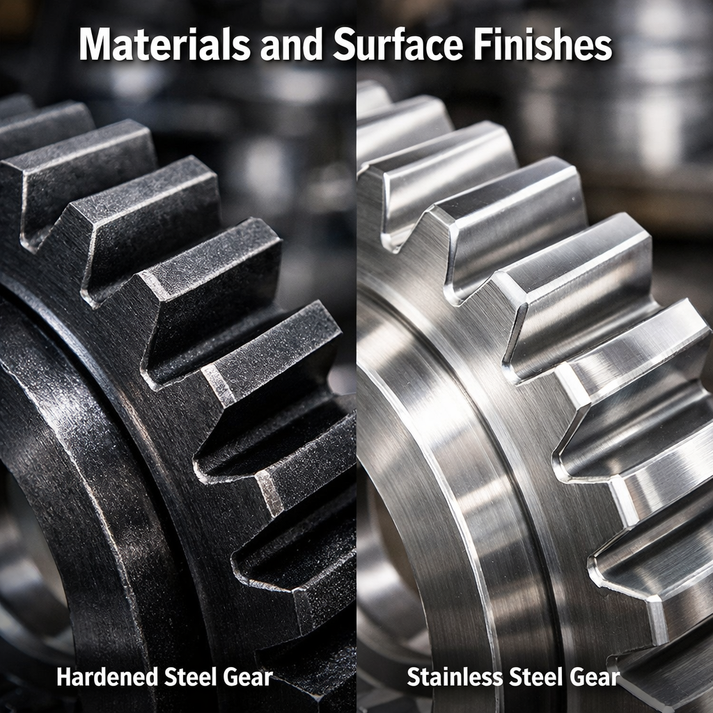
Material selection depends on your power requirements, with hardened alloy steels being the standard for high-torque industrial applications. When you design a spur gear, you must choose a material that can withstand the specific surface pressures in your machine. Material choice is the single most important factor in determining the ultimate power capacity of your gear set.
Hardening for high-torque loads
Unhardened steel gears are easy to machine but wear out quickly under the heavy loads found in industrial drives. If your application involves high torque, you should specify carburized or induction-hardened alloy steels for better performance. These processes create a hard, wear-resistant outer shell while keeping the core tough enough to absorb sudden shocks.
When should you use synthetics?
Are you designing for a wash-down environment or an application that requires no oil due to contamination risks? You should look into high-performance polymers like MC Nylon or POM for their self-lubricating properties and noise reduction. These materials are ideal for food processing or office equipment where traditional greases are strictly prohibited.
Key Takeaway: Match your material choice to both the load requirements and the environmental conditions of the workspace.
| Material Group | Surface Hardness | Best Environment |
|---|---|---|
| Hardened Steel | Very High | Industrial / High Load |
| Engineering Plastics | Low | Clean / Low Torque |
Analytical Guide: Material selection determines the limit of power density while acting as the ultimate constraint on physical size.
How wide should the face be when you design a spur gear?
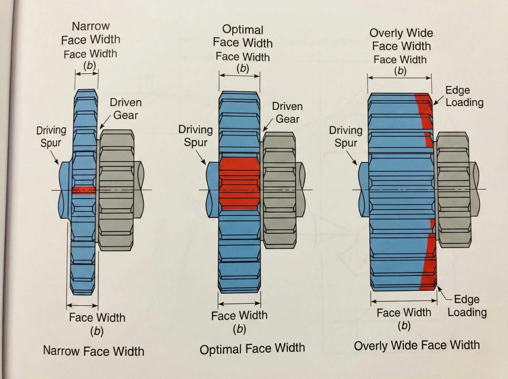
The face width should typically be between 8 and 14 times the module value to provide sufficient load area without becoming overly sensitive to shaft misalignment. When you design a spur gear, you must calculate a width that prevents tooth pitting by distributing forces effectively. A balanced face width ensures maximum torque capacity without compromising mechanical stability.
Managing the width-to-diameter ratio
If you make the gear too wide, any slight bending of the shaft will cause the load to concentrate on one edge. This edge loading leads to rapid and localized failure even if the gear material is high-quality hardened steel. You should aim for a balanced ratio that provides strength while allowing for minor manufacturing tolerances in the housing.
Why does alignment limit width?
You must realize that wider gears require much more rigid housings and precision-aligned bearings to function correctly over time. If your gearbox housing is prone to flexing under load, a narrower gear might actually last longer due to better contact. Simply put: don’t build a wide gear unless you can guarantee the shafts will stay perfectly parallel.
Key Takeaway: Increasing face width increases torque capacity provided that shaft alignment remains absolutely perfect.
| Face Width Ratio | Sensitivity | Strength |
|---|---|---|
| 8 × Module | Low | Moderate |
| 12 × Module | High | High |
Analytical Guide: Optimizing face width requires assessing housing rigidity since wider gears are useless if the casing allows deflection.
Do tolerances matter when you design a spur gear?
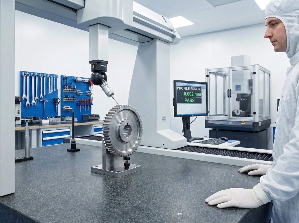
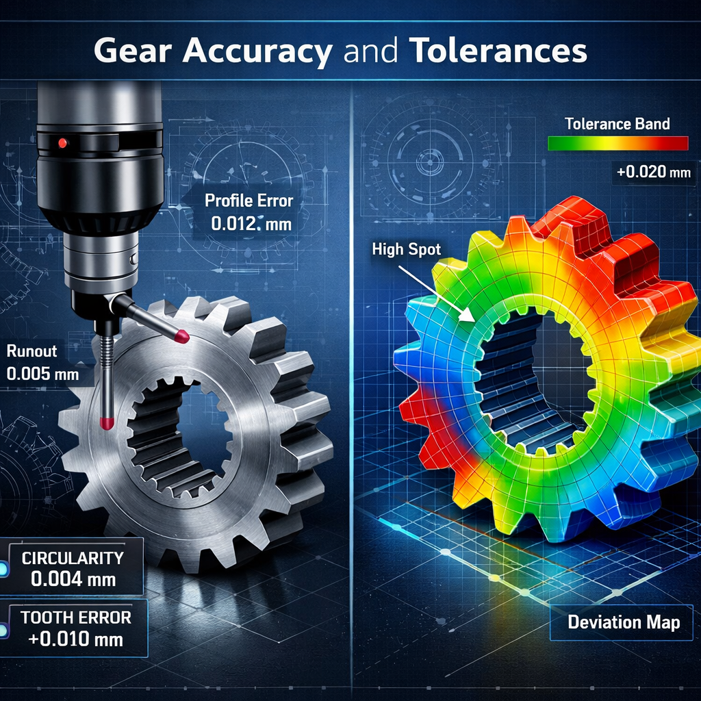
Tolerances matter because they define the accuracy grade of the gear, which directly impacts noise, vibration, and performance at high rotational speeds. To design a gear that meets modern standards, you must specify tolerances for pitch error and runout using ISO or AGMA grades. Higher precision ensures that the teeth mesh perfectly at every point in the rotation cycle.
Grading for noise and vibration
Higher precision grades significantly reduce the noise and vibration generated by the gear set during operation. If you are designing a high-speed blower, you should specify ground gears with an ISO grade of 6 or 7. For slow-moving conveyors, a milled gear with a grade of 9 or 10 is usually more than adequate.
Is high precision worth the cost?
Manufacturing costs increase exponentially as you demand tighter tolerances for your custom gear components. It is your job as a designer to find the “sweet spot” where the gear is accurate enough without over-specifying. Most industrial power transmission needs are met perfectly by standard hobbed gears without the need for expensive secondary grinding.
Key Takeaway: Higher precision grades reduce noise and heat but increase manufacturing complexity and cost exponentially.
| Accuracy Class | Manufacturing Method | Best Application |
|---|---|---|
| Precision | Grinding | Aerospace / Robotics |
| Commercial | Hobbing | General Industry |
Analytical Guide: Tolerance specification remains the final bridge between theoretical design and a functional machine for operational success.
Conclusion
Understanding the intricate geometry and design shapes of spur gears is the first step toward building machinery that lasts for decades. By carefully selecting your modules, tooth counts, materials, and tolerances, you can eliminate the risk of failure and ensure smooth power transmission. We are dedicated to providing the precision components your business needs to stay ahead of the competition. If you need help with your next project or require custom-engineered solutions, contact us today to start a conversation with our expert team.
FAQ Section
Q1: What’s the best pressure angle for high-torque applications?
The 20-degree angle is the best choice because it provides a thicker tooth base that resists bending and breaking under extreme loads.
Q2: Can I use different modules for mating gears?
No, mating gears must have the exact same module to ensure the teeth mesh correctly and transmit power without jamming.
Q3: How do I know if I need a hardened material?
You know it is necessary if your application involves high surface pressures, heavy shock loads, or if you require a long service life.
Q4: What’s the best way to reduce noise in a gear set?
Increasing the number of teeth to improve the contact ratio and specifying higher precision accuracy grades like ISO 6 are the best methods.
Q5: Can I design a gear with zero backlash?
Yes, but you should only do so for precision positioning systems using specialized anti-backlash gears, as standard gears will overheat and seize.