You often face significant frustration when standard CAD tools provide merely approximate tooth profiles that fail during advanced motion analysis. This lack of precision leads to interference issues in assemblies and unreliable simulation data for high-stress applications. You can solve this by creating a parametric spur gear model using equation-driven curves to mirror real-world physics. Our engineering team at Yantong Tech specializes in delivering stable, industrial-grade transmission components based on these rigorous mathematical foundations.
1. Why is an accurate spur gear model necessary?
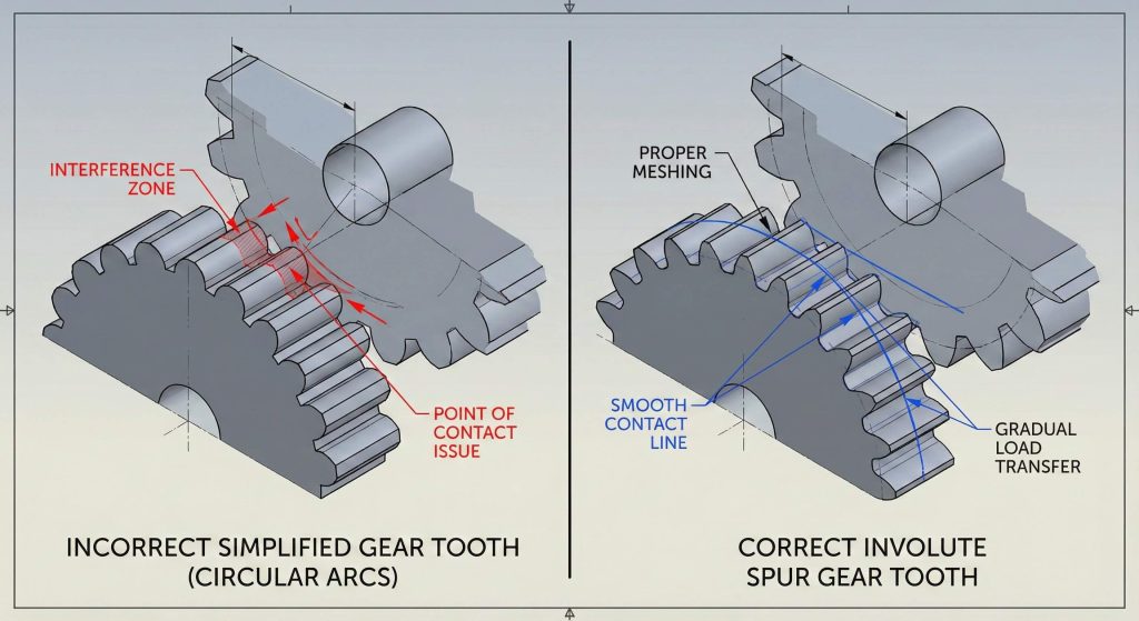
Standard library components frequently use simplified arcs that do not represent the actual contact path between meshing teeth. This discrepancy results in catastrophic mechanical failure when parts are manufactured via CNC machining or 3D printing. Ready for the good part? A high-fidelity spur gear model ensures that your design maintains constant angular velocity ratios throughout its rotation.
Does model accuracy impact simulation?
Exact tooth geometry ensures that contact stresses are distributed correctly across the flank surface. Generic models create artificial stress concentrations that do not exist in physical hardware.
- Reliable load distribution analysis.
- Precise 3D printing results.
- Reduced noise during high-speed operation.
- Exact backlash control.
Key Takeaway: Mathematical precision in the tooth profile is the foundation of reliable FEA results and functional prototyping.
| Requirement | Simplified Model | Parametric Model |
|---|---|---|
| Motion Analysis | Approximate | Exact |
| Manufacturing | Visual Only | Production Ready |
| Simulation | High Error Risk | Validated Results |
Analysis of these requirements shows that only parametric modeling supports high-stakes industrial manufacturing and simulation accuracy.
2. How does involute geometry define a spur gear model?
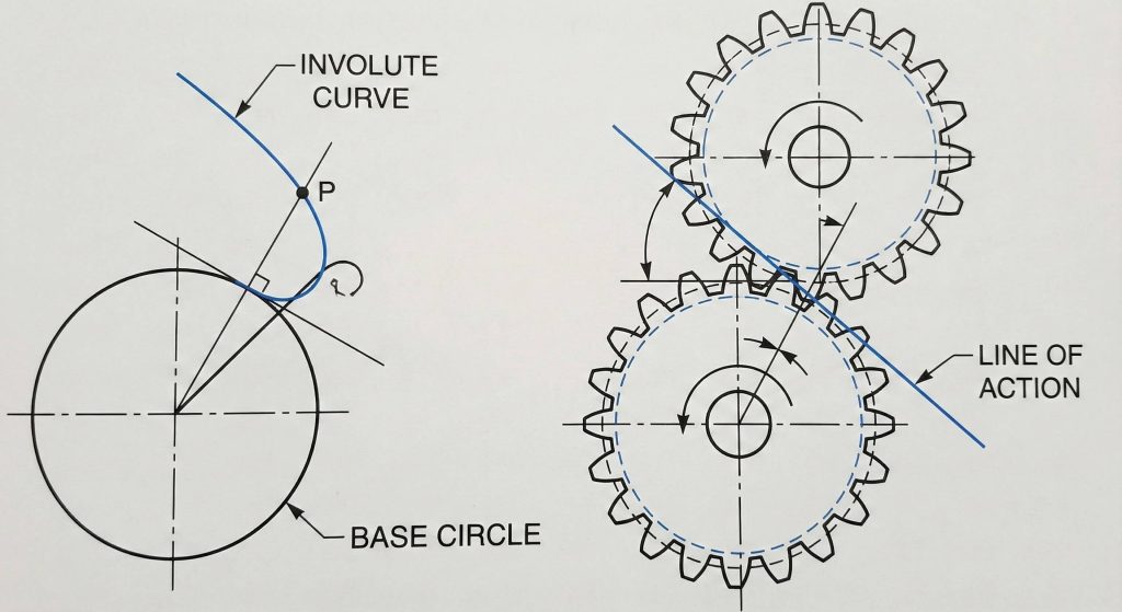
Involute curves define the tooth profile by ensuring that meshing surfaces maintain a constant line of action during rotation. This geometry allows gears to transmit power smoothly even if the center distance varies slightly between shafts. But here is the kicker. This same precision is vital for other components, such as a bevel gear, where intersecting shafts require perfect tooth engagement.
Why is the line of action significant?
A constant line of action ensures that the force vector between teeth remains stable during the entire mesh cycle. This stability prevents torque ripples that could damage sensitive downstream components.
- Uniform motion transmission.
- Constant pressure angle.
- Tolerance for center distance variation.
Key Takeaway: Involute geometry transforms rotational force into predictable linear motion along a fixed, stable path.
| Geometric Feature | Property | Mechanical Benefit |
|---|---|---|
| Involute Curve | Mathematical | Smooth Engagement |
| Line of Action | Straight | Stable Torque |
| Tooth Flank | Precise | Minimal Wear |
The stable force vector provided by the line of action is the primary reason involute geometry remains the global industrial standard.
3. Which parameters drive a parametric spur gear model?
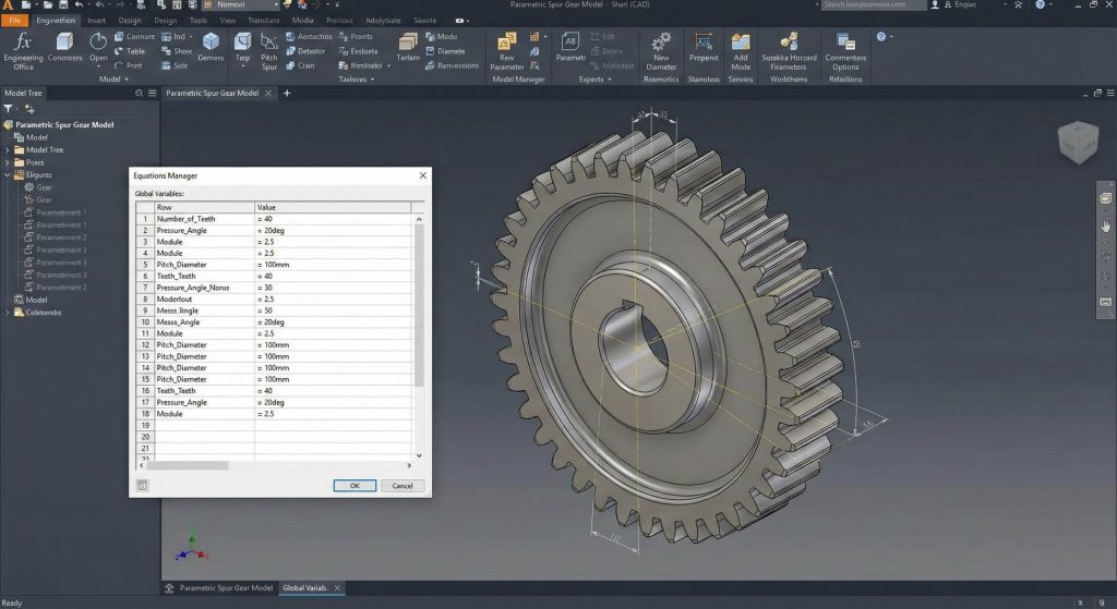
Diametral pitch and pressure angle serve as the primary variables that dictate the overall size and strength of your gear. You must establish these relationships early in your spur gear model to prevent manual rework when design requirements change. What is the real story? Linking these parameters through the Equations Manager rather than hard-coding dimensions allows a single file to represent thousands of configurations.
How do global variables simplify design?
Global variables act as a master control panel for your entire geometric feature tree. Modifying one value in the manager triggers an automatic update for every downstream sketch and pattern.
- Diametral Pitch (P).
- Pressure Angle (Alpha).
- Number of Teeth (Z).
- Face Width (S).
Key Takeaway: Centralizing your driving parameters in the Equations Manager creates a “master” file for rapid design iteration.
| Variable | Description | Impact |
|---|---|---|
| Pitch (P) | Teeth per inch | Tooth Size |
| Alpha | Pressure Angle | Load Capacity |
| Z | Teeth Count | Diameter |
Using global variables transforms a static CAD part into a dynamic engineering tool capable of scaling with project needs.
4. How to start sketching the basic spur gear model?
Beginning your model requires two concentric circles representing the bore diameter and the tooth tip diameter. These circles form the “blank” feature from which you will eventually cut the gear teeth. Ready for more? Extruding this sketch creates the physical volume of the gear body required for torque simulation.
Should you use construction geometry?
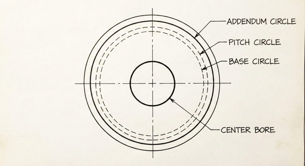
Reference circles for pitch and base diameters must remain as construction lines to avoid interfering with solid boss features. These lines provide the necessary mathematical anchors for the involute curves you will plot later.
- Pitch circle diameter.
- Base circle diameter.
- Addendum and dedendum.
Key Takeaway: A well-organized master sketch prevents reconstruction errors during complex geometric updates or feature rebuilds.
| Circle Type | Geometry Style | Purpose |
|---|---|---|
| Addendum | Solid | Outer Bound |
| Pitch | Construction | Mesh Point |
| Base | Construction | Involute Origin |
Proper use of construction geometry ensures that the sketch remains clean and the parametric links remain robust during resizing.
5. What equations generate a true spur gear model?
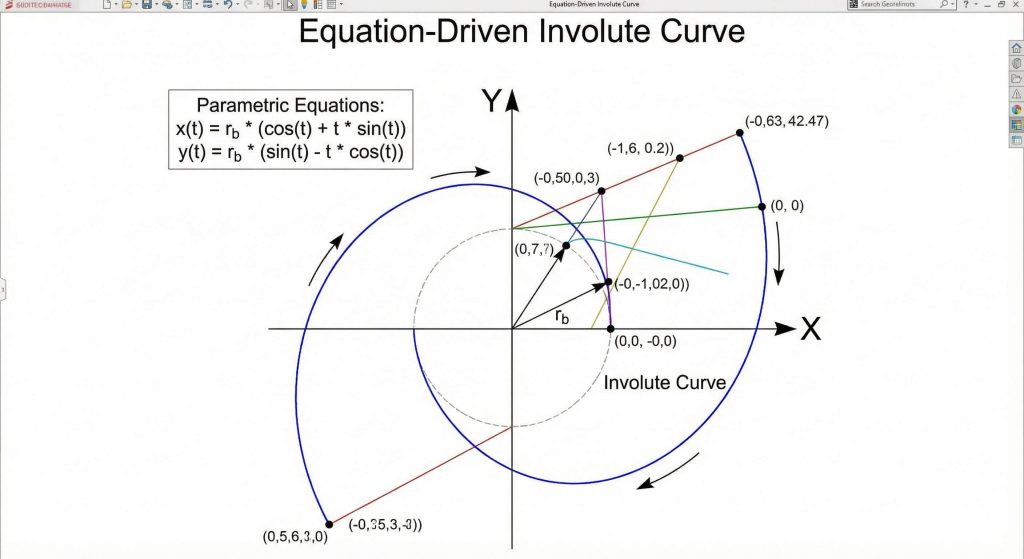
Parametric equations using “t” as a variable define the X and Y coordinates of the involute curve relative to the base circle. You will utilize the “Equation-Driven Curve” tool in your spur gear model to plot these points with theoretical perfection. This is where it gets interesting. You can apply similar logic to a gear rack where the linear pitch must match the circular pitch of the gear.
How do you determine the ‘t’ range?
The variable “t” represents the radians of a virtual string unwound from the base circle cylinder. You must set start and end values to ensure the curve spans from the base circle to the tip diameter.
- X = R * (cos(t) + t * sin(t)).
- Y = R * (sin(t) – t * cos(t)).
- R = Base Circle Radius.
Key Takeaway: Equation-driven curves provide the highest possible geometric fidelity for generating CNC toolpaths or high-resolution STL files.
| Equation Element | Component | Role |
|---|---|---|
| X Coordinate | Cosine Factor | Horizontal Plot |
| Y Coordinate | Sine Factor | Vertical Plot |
| Parameter ‘t’ | Variable | Curve Resolution |
Implementing parametric equations removes the inaccuracies inherent in manual sketching and ensures perfect tooth engagement every time.
6. How to create the tooth profile for your spur gear model?
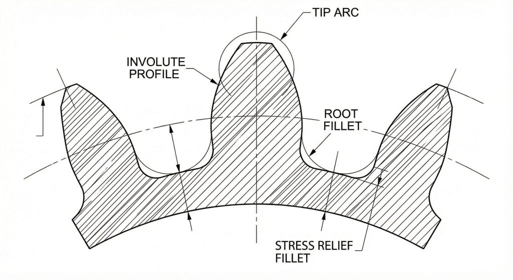
Creating the profile involves mirroring your initial involute curve across a radial construction line to form a complete, symmetric tooth. You must then close the contour by adding arcs for the root and the tip surfaces. Here is the deal. You may also need to model an internal gear using inverted logic for compact planetary transmission systems.
Why are root fillets necessary?
Sharp corners at the base of a tooth act as stress risers that lead to premature fatigue cracks. Modeling a small radius at the root improves the structural integrity and durability of the physical part.
- Stress relief radii.
- Tangency constraints.
- Symmetric mirroring.
Key Takeaway: Closing the profile with properly scaled fillets ensures both manufacturability and long-term mechanical reliability.
| Tooth Feature | Construction Tool | Mechanical Purpose |
|---|---|---|
| Flank | Involute Curve | Power Transfer |
| Root Fillet | Sketch Fillet | Fatigue Prevention |
| Tip Arc | Centerpoint Arc | Clearance Control |
A complete tooth profile serves as the master seed for the circular patterns that define the final gear geometry.
7. Can circular patterns automate the spur gear model?
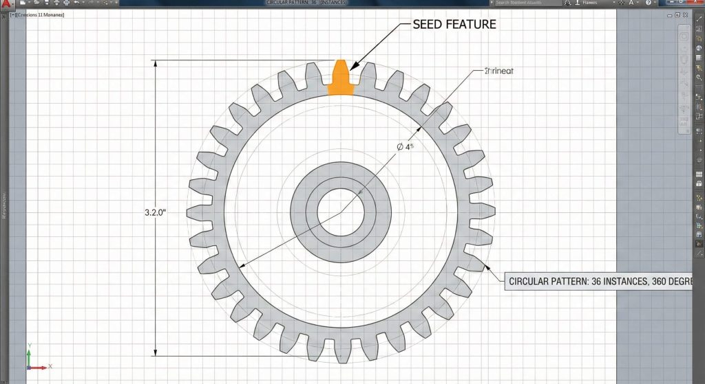
Circular patterns allow you to replicate a single tooth cut around the entire circumference of your gear blank automatically. Link the number of instances in the pattern directly to your “Number of Teeth” global variable in the spur gear model. You might be wondering. Does this link maintain accuracy? Yes, the software automatically redistributes the teeth evenly over 360 degrees whenever the count changes.
How do you verify the tooth pattern?
Inspect the final tooth for overlap or gaps at the root circle once the pattern rebuilds. If your initial tooth width was calculated correctly based on circular pitch, the pattern will close perfectly without errors.
- Equal spacing option.
- Instance count link.
- Geometry pattern selection.
Key Takeaway: Linking patterns to global variables makes your model truly “smart” and adaptable for rapid transmission prototyping.
| Pattern Variable | Source | Automation Result |
|---|---|---|
| Instance Count | Global Variable ‘Z’ | Adaptive Teeth |
| Pattern Angle | 360 Degrees | Even Distribution |
| Feature Type | Cut-Extrude | Material Removal |
Automation via circular patterns reduces human error and ensures that the gear remains geometrically valid across all configurations.
8. How to update dimensions in a dynamic spur gear model?
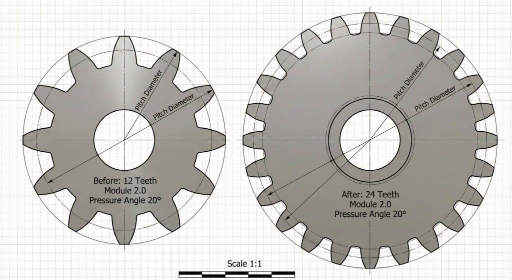
Updating dimensions requires only a simple change to the input values within your master Equations Manager window. Once you modify the diametral pitch, the entire model rebuilds based on the new mathematical relationships. Ready for the good part? This flexibility is equally useful when designing helical gear sets that require specific helix angles and face widths.
What happens if the model breaks?
Invalid geometry occurs if you input a tooth count that is physically impossible for the given pitch circle. You can usually resolve these rebuild errors by adjusting your root fillet sizes or checking your sketch constraints.
- Rebuild active document.
- Verify pitch diameter.
- Adjust fillets if needed.
Key Takeaway: Parametric modeling turns a static CAD file into a versatile design tool for iterating through complex transmission ratios.
| Update Action | System Response | Engineer’s Goal |
|---|---|---|
| Edit Global Variable | Automatic Rebuild | Rapid Iteration |
| Change Pitch | Rescale Profile | Size Optimization |
| Adjust Teeth Count | Pattern Update | Ratio Variation |
The ability to resize models instantly allows engineering teams to explore multiple design paths in a fraction of the traditional time.
9. How to optimize performance for a large spur gear model?
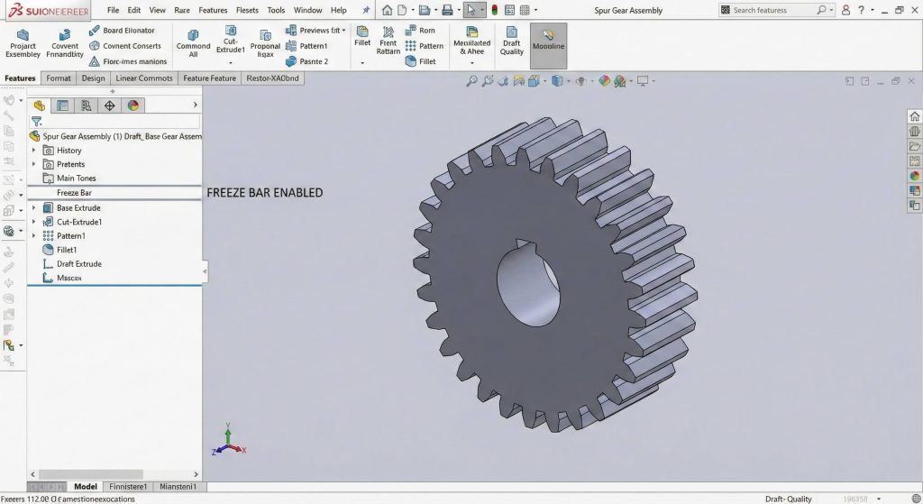
Optimizing performance involves freezing the feature tree once your high-fidelity spur gear model reaches its final design state. CAD programs often struggle to recalculate hundreds of complex involute faces during assembly rotations or drawing creation. What is the catch? While freezing helps, you must remember to unfreeze the bar if you need to make further parametric changes.
Does graphical detail matter for rebuilds?
High-quality image settings in your CAD software can bog down performance without adding any functional engineering value. Lowering the “Image Quality” slider in your document properties can make rotating large gear sets significantly smoother.
- Use the Freeze Bar.
- Simplify display quality.
- Suppress cosmetic features.
Key Takeaway: Managing rebuild times is just as important as the geometry itself when working on professional-grade industrial projects.
| Optimization Tool | Action | Performance Gain |
|---|---|---|
| Freeze Bar | Lock Features | Zero Rebuild Time |
| Image Quality | Lower Slider | Faster Graphics |
| Parasolid Export | Remove History | Instant Loading |
Performance optimization ensures that your workstation remains responsive even when handling massive assemblies with thousands of teeth.
10. Where can you source a custom spur gear model?
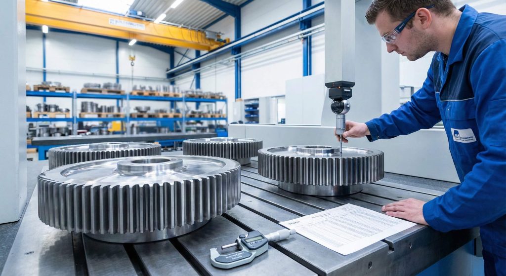
Professional manufacturing partners like Yantong Tech offer direct engineering support to transform your CAD files into physical industrial components. While modeling gears is excellent for validation, production requires specialized hobbing and grinding equipment to achieve the required tolerances. Sourcing from a specialist who understands the nuances of a gear shaft ensures your precision translates to performance.
How do you prepare files for a quote?
Ensure your 3D model is accompanied by a detailed 2D drawing showing tolerances, surface roughness, and specific heat treatment requirements. Clear communication regarding the application environment helps the manufacturer select the best steel grade for the job.
- Submit STEP or Parasolid files.
- Specify material certifications.
- Request inspection reports.
Key Takeaway: A perfect CAD model is the first step; professional manufacturing brings that precision to life with traceable quality.
| Sourcing Step | Documentation | Final Result |
|---|---|---|
| Inquiry | 3D CAD + 2D Print | Accurate Quote |
| Validation | Inspection Report | Quality Assurance |
| Delivery | Material Certs | Reliable Service |
Partnering with an expert manufacturer bridges the gap between a theoretical digital design and a functional, long-lasting industrial product.
Conclusion
Modeling accurate involute spur gears depends on using equation-driven curves rather than simplified approximations. This technical guide outlined how to establish global variables and use parametric formulas to generate true-to-form tooth geometry. We explored the significance of the involute profile for uniform motion and emphasized the power of automation through circular patterns. Remember that while a smart model provides a solid design foundation, the ultimate success of your transmission depends on professional manufacturing and material selection. Take your verified CAD files to Yantong Tech to ensure your vision operates flawlessly. To get started, contact us today to discuss your specific needs. Our brand vision is to provide reliable transmission components through genuine manufacturing and continuous improvement.
FAQ
- Can I model metric gears using this spur gear model?
Yes, you simply replace the Diametral Pitch (P) with the Metric Module (m) in your equations and ensure your units are set to millimeters. - What’s the best way to handle tooth fillets in a spur gear model?
The best practice is to tie the fillet radius to a global variable like ‘clearance’ so the root geometry scales automatically when you resize the gear. - How do I know if the pressure angle is correct?
A standard 20-degree pressure angle provides a balance of strength and efficiency; you can verify it by checking the base circle diameter in your model. - Can I use this spur gear model for helical gears?
You can use the same involute profile sketch, but you must extrude it using a ‘Helix’ or ‘Sweep’ feature along a twisted path rather than a straight extrusion. - What’s the best way to reduce rebuild times?
Using the Freeze Bar in the feature tree is the most effective method to stop unnecessary calculations once the tooth geometry is finalized.