Helical gear calculations require a precise transformation of normal plane specifications into radial plane geometries to ensure mechanical compatibility. Engineers often struggle with the diverging requirements of normal and radial systems, leading to interference or excessive noise in power transmission. A single error in calculating the profile shift or helix angle can result in catastrophic failure or incompatible center distances during assembly. Our comprehensive helical gear formulas provide the geometric principles and mathematical steps required to design reliable helical, crossed helical, and bevel gear systems.
How do normal and radial systems differ?
The primary difference lies in the plane of reference; the normal system references the tooth profile perpendicular to the helix, while the radial system references the plane perpendicular to the gear axis. To accurately convert between these, engineers use helical gear formulas that apply the cosine of the helix angle to the module and pressure angle. This ensures the teeth mesh correctly in the axial direction for smooth rotation.

Understanding Pitch Planes
Here is the deal. The transverse pitch is always larger than the normal pitch because it is measured along the rotation plane.
- Normal Module ($m_n$): The base profile perpendicular to the tooth.
- Transverse Module ($m_t$): Calculated as $m_n / \cos(\beta)$.
- Helix Angle ($\beta$): The angle of the tooth inclination.
Mathematical Transformation
Key Takeaway: Transforming module and pressure angles ensures the gear geometry matches the manufacturing tool while meeting the assembly requirements of the radial plane.
| Pitch Type | Measurement Plane | Mathematical Relation |
|---|---|---|
| Normal | Perpendicular to tooth | Base Reference |
| Transverse | Perpendicular to axis | $m_n / \cos(\beta)$ |
The transverse module is the critical factor in determining the final pitch diameter for any helical gear set.
What are the key helical gear formulas for profile shift?
Profile shifting is utilized to adjust center distances and improve tooth strength. In the normal system, calculation involves determining the working pitch diameter and working pressure angle through helical gear formulas that adjust for the helix angle. This methodology allows for customized tooth thickness to prevent undercutting in pinions with low tooth counts.
Shifting the Pitch Line
Think about it. A small shift in the tool position during manufacturing completely changes the gear performance. Profile shifting is essential for maintaining standard center distances when the tooth count is non-standard.
- Positive Shift: Increases tooth thickness and strength.
- Negative Shift: Decreases thickness, often used for larger gears.
- Working Pressure Angle: Changes based on the shift coefficient.
Geometric Stability
Key Takeaway: Balancing shift coefficients between the pinion and gear optimizes durability and reduces operating noise in high-load applications.
| Coefficient | Effect on Tooth | Application |
|---|---|---|
| Positive (x > 0) | Wider root, thinner tip | High-load pinions |
| Negative (x < 0) | Thinner root | Large mating gears |
Strategic profile modification is the primary defense against pinion tooth weakening in high-torque environments.
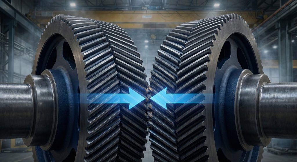
How do Sunderland double helical gears work?
Sunderland double helical gears utilize specific helical gear formulas where the radial pressure angle is 20 degrees and the helix angle is fixed at 22.5 degrees. This configuration allows the V-shaped tooth structure to balance axial thrust forces internally without requiring specialized bearings. The system relies on unique addendum and whole depth calculations to accommodate the specific Sunderland manufacturing machine requirements.
Fixed Geometric Constraints
The bottom line. Standardizing the helix angle simplifies the manufacturing of massive industrial herringbone gears. This consistency provides predictable power transmission across heavy-duty equipment.
- Helix Angle: Fixed at 22.5° for double helical sets.
- Radial Pressure Angle: Standardized at 20°.
- Tooth Shape: V-pattern to cancel axial thrust.
Sunderland Depth Parameters
Key Takeaway: The Sunderland system modifies standard radial depth parameters to provide the high load capacity required for large-scale industrial machinery.
| Feature | Sunderland Standard | Engineering Benefit |
|---|---|---|
| Helix Angle | 22.5 Degrees | Balanced Axial Forces |
| Tooth Depth | Modified ($2.188m$) | High Load Capacity |
Internal thrust cancellation makes these gears ideal for heavy machinery without needing complex and expensive bearing layouts.
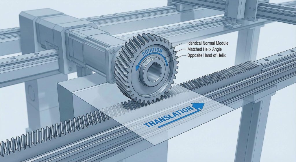
What defines a helical rack and gear mesh?
A helical rack mesh is geometrically equivalent to a spur gear and rack when viewed in the normal direction. Successful engagement requires the gear and rack to share the same normal module and pressure angle while using opposite hands according to helical gear formulas. One full rotation of the gear translates into linear displacement equal to the product of the number of teeth and the transverse pitch.
Linear Displacement Logic
It gets better. The travel of the rack is directly proportional to the radial pitch of the mating gear. Using helical racks results in much smoother motion than standard spur rack systems.
- Hand Direction: Must be opposite (Left meshes with Right).
- Module: Must be identical in the normal plane.
- Displacement: Constant per turn based on transverse pitch.
Matching Helix Angles
Key Takeaway: Helical racks provide smoother linear motion than spur racks due to the gradual engagement of the slanted teeth.
| Interaction Component | Compatibility Rule | Calculation |
|---|---|---|
| Hand Direction | Must be Opposite | Left meshes with Right |
| Displacement | Constant per turn | $z \times m_n \times \pi / \cos(\beta)$ |
Consistent radial pitch calculation is the foundation of precise and quiet linear motion systems in B2B applications.
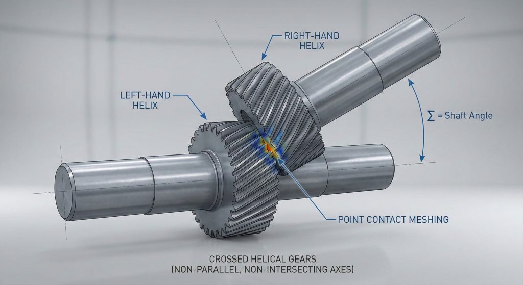
How do crossed helical gears connect skew shafts?
Crossed helical gears connect non-parallel, non-intersecting shafts by utilizing helical gear formulas that allow for different helix angles on each gear. The shaft angle is defined as the sum or difference of these angles, provided the normal modules of both gears are identical. Unlike parallel shaft systems, the velocity ratio in crossed meshes is determined strictly by the tooth count rather than the pitch diameter ratio.
Skew Shaft Angles
You might be wondering. How is the ratio calculated if the diameters are different? In crossed helical meshes, the contact remains at a point rather than along a line.
- Shaft Angle ($\Sigma$): The total angle between axes.
- Normal Module: Must be identical for both gears.
- Helix Hand: Can be the same depending on the shaft angle.
Point Contact Dynamics
Key Takeaway: Crossed helical gears provide exceptional design flexibility for connecting shafts at various angles but are limited by point contact load capacities.
| Variable | Crossed Helical Rule | Comparison to Parallel |
|---|---|---|
| Velocity Ratio | $z_2 / z_1$ | Same as Parallel |
| Helix Hand | Often same hand | Must be opposite |
Velocity ratios in skew systems remain independent of diameter variations, which greatly simplifies complex drivetrain layouts for engineering teams.
How is the center distance for screw gears calculated?
The center distance for screw gears is determined by summing the pitch diameters of each gear and dividing the result by two. Engineers apply helical gear formulas to allow for significant flexibility in center distance by slightly modifying the helix angle. Because the pitch diameters are functions of the helix angle, designers can tune the assembly to fit specific housing constraints without changing tooth counts.
Tuning Assembly Dimensions
But wait, there’s more. You can actually change the distance without changing the gear ratio. This is achieved by adjusting the helix angle, which directly alters the pitch diameter of the gear.
- Pitch Diameter ($d$): $z \times m_n / \cos(\beta)$.
- Center Distance ($a$): $(d_1 + d_2) / 2$.
- Adjustment: Slight helix changes allow for assembly tolerances.
Geometry Flexibility
Key Takeaway: Adjusting the helix angle provides a variable center distance without requiring a change in the total number of teeth.
| Design Goal | Adjustment Method | Result |
|---|---|---|
| Increase Distance | Decrease Helix Angle | Larger Pitch Diameter |
| Decrease Distance | Increase Helix Angle | Smaller Pitch Diameter |
Precise helix angle selection enables a perfect fit within fixed mechanical envelopes while maintaining the required transmission ratio.
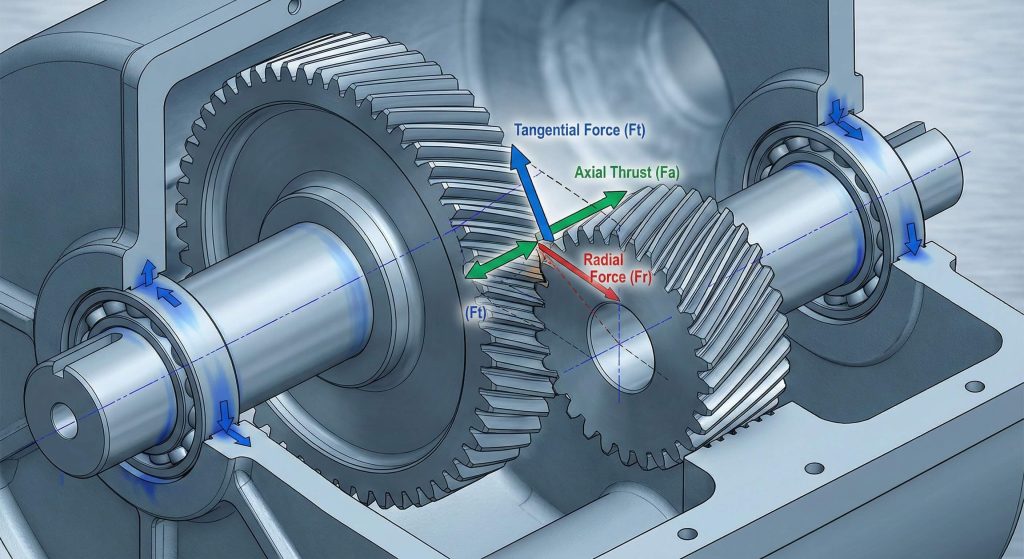
What causes axial thrust in helical gear sets?
Axial thrust is a resultant force generated by the helix angle of the teeth, calculated using helical gear formulas where the load is the tangential force multiplied by the tangent of the helix angle. This force requires specific bearing considerations to prevent axial displacement of the shafts during operation. Managing these forces is critical for the stability of high-speed transmission systems.
Managing Resultant Forces
The fact is. Ignoring axial thrust will lead to premature bearing failure and shaft misalignment. Helical gears decompose the total driving force into three distinct components.
- Tangential Force ($W_t$): The primary driving load.
- Axial Thrust ($W_T$): Force generated along the shaft.
- Bearing Choice: Must support both radial and thrust loads.
Bearing Selection Logic
Key Takeaway: High helix angles provide smoother operation but increase axial loads, necessitating the use of specialized thrust bearings or herringbone designs.
| Force Component | Calculation | Direction |
|---|---|---|
| Tangential | $2 \times \text{Torque} / d$ | Rotational |
| Axial Thrust | $W_t \times \tan(\beta)$ | Parallel to Shaft |
Balancing the helix angle involves a strategic trade-off between tooth overlap and the mechanical cost of axial load management.
How do bevel gears transmit power at right angles?
Bevel gears operate on the surface of a sphere, with pitch diameters belonging to frusta of cones meeting at a common apex. Designers utilize helical gear formulas to define the pitch cone angles, which are strictly determined by the gear ratio. Unlike cylindrical gears, all bevel gear dimensions and pitch diameters are referenced to the outer end, or heel, of the tooth.
Pitch Cone Intersections
Here’s the deal. Bevel gears are essentially cones rolling against one another without slippage. The pitch angle of each gear must be precisely calculated so the cones meet at a single common center.
- Pitch Angle ($\delta$): Determined by the ratio of teeth.
- Shaft Angle ($\Sigma$): Usually 90 degrees for standard drives.
- Miter Gears: Bevel gears with a 1:1 ratio.
Velocity Ratio Definitions
Key Takeaway: Bevel gear ratios are derived from the sine or tangent of the pitch angles, ensuring the cones roll without slipping.
| Parameter | 90-Degree Drive Rule | Miter Gear Case |
|---|---|---|
| Pitch Angle | $\tan(\delta_1) = z_1/z_2$ | Always 45 Degrees |
| Speed Ratio | $z_2/z_1$ | Always 1:1 |
Correct cone geometry is the only way to achieve conjugate engagement and smooth motion in intersecting shaft transmissions.
What are the benefits of spiral versus straight bevels?
Spiral bevel gears offer smoother and quieter operation because their curved teeth engage gradually, following the overlap principles of helical gear formulas. This gradual engagement allows them to handle significantly higher speeds and torque compared to straight bevels. While straight bevels are ideal for low-speed static loads, spiral bevels are the preferred choice for high-performance automotive and industrial applications.
Overlap and Efficiency
Ready for the good part? More teeth in contact means the load is distributed over a larger surface area. This reduces the stress on individual teeth and allows for a more compact gearbox design.
- Spiral Angle: The inclination of the tooth on the cone.
- Tooth Overlap: Ensures multiple teeth are always engaged.
- Vibration: Significantly lower than straight tooth forms.
Application Standards
Key Takeaway: Spiral bevels increase the load distribution across multiple teeth, reducing individual tooth stress and overall system vibration.
| Gear Type | Speed Limit | Noise Level |
|---|---|---|
| Straight Bevel | < 300 m/min | High |
| Spiral Bevel | > 300 m/min | Low |
Selecting the spiral tooth form is a strategic move for any high-frequency power transmission requirement involving intersecting shafts.
How are Gleason straight bevel gears calculated?
Gleason straight bevel gears follow a specific system where the whole depth is 2.188m and the pinion is positive-shifted to balance strength. These helical gear formulas ensure that the top clearance remains parallel along the entire tooth length. This standardization prevents undercutting in small pinions and ensures uniform gap distribution for better lubrication during operation.

Gleason System Standards
The bottom line. Gleason geometry provides a uniform gap between the tip of one tooth and the root of the mating gear. This parallel clearance is vital for maintaining a consistent lubrication film.
- Working Depth: Standardized at $2.000m$.
- Clearance ($c_a$): Standardized at $0.188m$.
- Pinion Shift: Always positive to prevent undercutting.
Strength Distribution
Key Takeaway: Shifting the pinion profile in the Gleason system prevents undercutting and balances the fatigue life between mating components.
| Gleason Parameter | Standard Value | Benefit |
|---|---|---|
| Whole Depth | $2.188m$ | Standardized Manufacturing |
| Clearance | Parallel | Consistent Lubrication |
Utilizing the Gleason system provides a robust manufacturing framework for high-quality, interchangeable bevel gear sets across various industries.
Conclusion
Mastering helical and bevel gear technology requires a rigorous approach to geometric transformations and load analysis. By resolving the complexities of normal versus radial systems and optimizing profile shifts, engineers can eliminate noise and prevent catastrophic mechanical failure. Our vision at Yantong Tech is to empower global equipment manufacturers with precision-engineered transmission components that offer full traceability and engineering-friendly communication. We have solved common problems involving axial thrust, center distance tuning, and tooth undercutting through advanced manufacturing standards. To optimize your next mechanical project with expert support and reliable components, contact us today.
Frequently Asked Questions (FAQ)
Can I use helical gears of the same hand on parallel shafts?
No. Parallel shaft helical gears must have opposite hands (one left-hand and one right-hand) to mesh properly; same-hand gears are reserved for crossed shaft applications.
What’s the best way to handle axial thrust in a helical system?
The best approach is to use thrust bearings or double helical designs that naturally cancel out axial forces within the gear body.
How do I know if I need a profile shift?
You generally need a profile shift if your pinion has fewer than 17 teeth to prevent undercutting or when you must match a non-standard center distance.
What’s the best application for Zerol bevel gears?
Zerol bevels are best for internal gear assemblies or precision components where you need smooth engagement without the end thrust of spiral bevels.
Can I adjust the center distance of a helical gear pair?
Yes. You can adjust the center distance by slightly modifying the helix angle or by applying profile shift coefficients to the gear set.