
Machining directly dictates gear rack dimensional tolerances by influencing the material removal rate, thermal expansion, and residual stress relief during the production cycle. Inconsistent machining parameters lead to cumulative pitch errors that compromise linear positioning and cause excessive mechanical vibration in high-load systems. Precision engineering partners mitigate these risks through controlled material removal and standardized spur gear tolerances across the entire rack length.
Why do spur gear tolerances matter for gear rack accuracy?
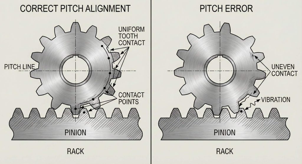
Spur gear tolerances define the infinite pitch radius relationship that ensures smooth engagement between a linear rack and its driving pinion. Deviations in these values cause uneven torque transmission and accelerated surface fatigue. Precision engineering requires adherence to strict geometric dimensioning and tolerancing (GD&T) to maintain operational stability.
Maintaining Pitch Line Consistency
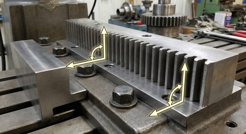
Pitch line consistency is the primary factor in determining the synchronous movement of the gear rack and pinion. Even minor deviations in height from the base to the pitch line will alter the center distance during operation.
Here is the kicker:
- Vertical alignment prevents tooth jamming.
- Consistent height reduces friction.
- Pitch accuracy enables high-speed travel.
Key Takeaway: Pitch line integrity is the foundation of linear motion precision.
| Parameter | Standard Tolerance (mm) | Impact of Deviation |
|---|---|---|
| Individual Pitch Error | ±0.020 | Localized vibration |
| Total Pitch Error | ±0.050 / 1000mm | Cumulative positioning lag |
High-precision gear racks rely on the meticulous alignment of the pitch line relative to the reference base surface.
How does tooth milling influence spur gear tolerances on racks?
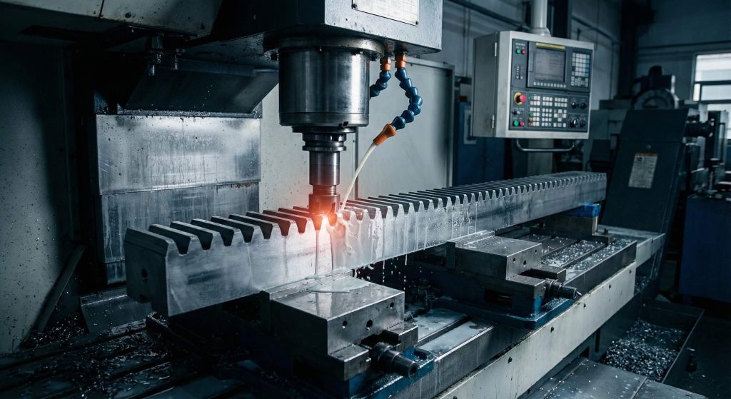
Tooth milling sets the initial profile of the gear teeth, and spur gear tolerances are heavily influenced by the speed and feed rates used during this material removal phase. Excessive heat generated during milling can cause the steel bar to expand, leading to tooth spacing errors once the part cools. Specialized manufacturers use advanced cooling protocols to maintain a stable environment for consistent cutting.
Managing Thermal Drift During Cutting
Thermal drift occurs when the cutting tool generates more heat than the coolant can dissipate effectively. This leads to a gradual shift in the tooth profile as the rack progresses through the machine.
But wait, there is more:
- High-speed steel cutters require constant lubrication.
- Carbide inserts reduce thermal transfer to the workpiece.
- Variable feed rates prevent localized overheating.
Key Takeaway: Controlled milling speeds prevent thermal-induced dimensional inaccuracy.
| Milling Type | Surface Finish (Ra) | Typical Tolerance Grade |
|---|---|---|
| Rough Milling | 6.3 – 12.5 | ISO 10-12 |
| Finish Milling | 1.6 – 3.2 | ISO 8-9 |
Mechanical stability in linear gearing starts with the management of heat-induced expansion during the primary milling stage.
Can residual stress affect spur gear tolerances after machining?
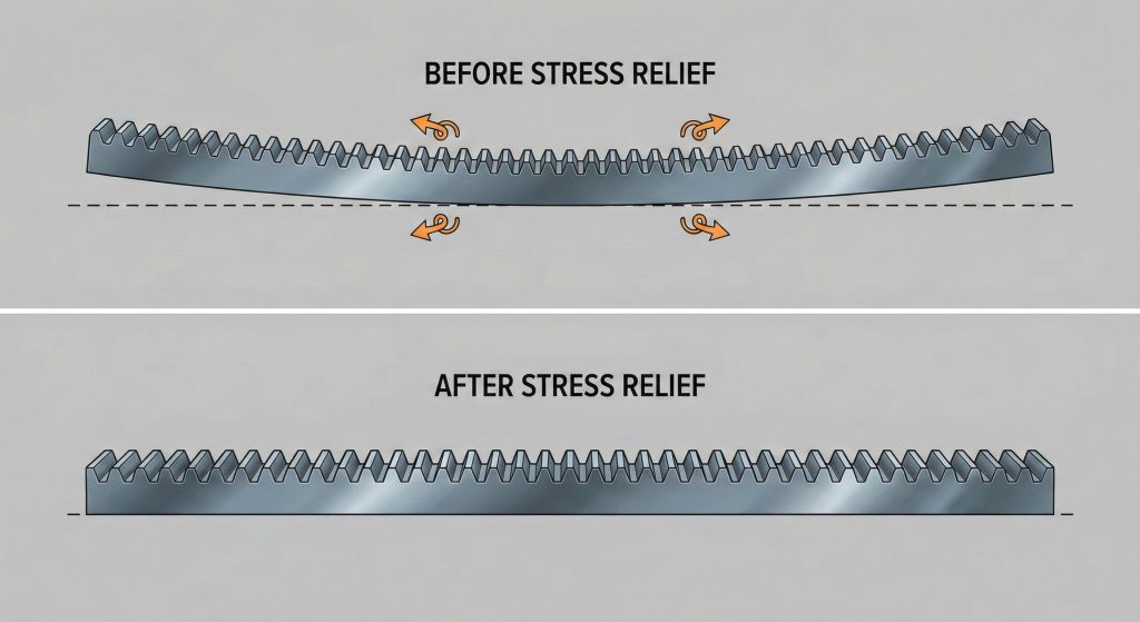
Residual stress affects the flatness of the gear rack base, often causing the material to bow or warp after the teeth have been cut. As material is removed from the top face, the internal stresses of the steel bar are released, leading to a phenomenon known as spring-back. This lack of flatness directly interferes with the mounting process and the final gear alignment.
Correcting Material Bowing Through Straightening
Material bowing is typically corrected using hydraulic presses that force the rack back into a straight profile. Without this secondary process, the rack would exhibit significant deviation over its total length.
What is the real story?
- Cold-drawn bars have higher residual stress.
- Stress-relieving heat treats can stabilize the material.
- Straightening must occur before final grinding.
Key Takeaway: Straightness is a post-machining requirement to ensure linear truth.
| Material Condition | Stress Level | Straightness Deviation |
|---|---|---|
| As-Drawn | High | 0.5mm / 1000mm |
| Stress Relieved | Low | 0.1mm / 1000mm |
Residual stress management is a non-negotiable step for any rack intended for high-precision industrial automation.
Does grinding improve spur gear tolerances for hardened racks?
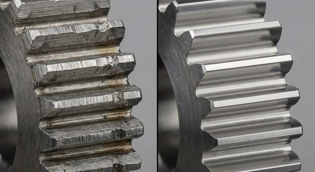
Grinding significantly improves spur gear tolerances by removing the distortions caused by hardening processes and achieving sub-micron surface finishes. It is the only reliable method for correcting pitch line shifts and maintaining parallelism across the side and bottom faces of the rack. Hardened and ground racks offer the highest level of positioning accuracy available in linear motion.
Achieving Sub-Micron Parallelism
Parallelism ensures that the side faces of the rack are perfectly aligned with the tooth path. This prevents the pinion from walking or scrubbing against the gear teeth during travel.
Here is the catch:
- Ground surfaces reduce frictional power loss.
- High-grit wheels produce superior tooth profiles.
- Grinding removes decarburized layers from heat treatment.
Key Takeaway: Precision grinding is the gold standard for high-performance linear motion.
| Process Stage | Profile Accuracy | Surface Roughness (Ra) |
|---|---|---|
| Milled Only | ±0.030 | 3.2 |
| Precision Ground | ±0.005 | 0.8 |
The transition from milling to grinding elevates a standard gear rack to a precision component suitable for robotics.
How do mounting surfaces impact spur gear tolerances in assembly?
Mounting surfaces dictate the final perpendicularity of the gear rack, ensuring that the teeth remain square to the driving pinion after installation. If the side or bottom faces are not machined with the same care as the teeth, the assembly will suffer from misalignment. Precision engineering partners prioritize the finishing of all six surfaces to guarantee system stability.
Perpendicularity in Rack Installation
Perpendicularity refers to the 90-degree relationship between the mounting base and the vertical axis of the gear teeth. Errors in this geometric feature lead to uneven tooth loading and noise.
The bottom line is this:
- Machined shoulders provide a reference for alignment.
- Dowel holes must be precisely positioned.
- Surface flatness prevents stress concentrations.
Key Takeaway: Stable mounting surfaces prevent secondary deviations during mechanical operation.
| Feature | Importance | Tolerance Requirement |
|---|---|---|
| Base Flatness | High | 0.02 / 1000mm |
| Side Squareness | Critical | 0.01 / 100mm |
Consistent mounting geometry ensures that the theoretical precision of the gear teeth is realized in the actual application.
Why is length control vital for spur gear tolerances on racks?
Length control is essential for ensuring that spur gear tolerances are maintained when multiple racks are joined end-to-end for long-travel systems. Racks must be machined slightly undersized to allow for a small gap that facilitates a continuous tooth pitch across the joint. Without precise length management, the pinion will experience a “jump” or interference at every rack transition.
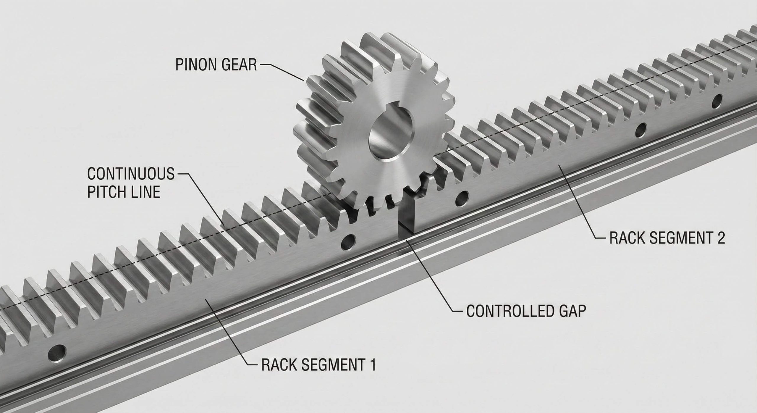
Engineering the Continuous Pitch Joint
Continuous pitch joints require a specific calculated gap between two adjacent racks to mimic a single long component. This gap accounts for thermal expansion and the manufacturing tolerances of the individual segments.
Make no mistake:
- Undersized lengths prevent physical interference.
- Alignment tools must bridge the joint during setup.
- Thermal expansion gaps prevent rack buckling.
Key Takeaway: Length tolerances are the secret to seamless long-distance linear travel.
| Travel Length | Expansion Gap (mm) | Adjustment Method |
|---|---|---|
| 1000mm | 0.1 – 0.2 | Precision gauge block |
| 5000mm+ | 0.5 – 1.0 | Floating mount system |
Accurate length control allows engineers to create infinite linear travel paths without losing tooth engagement accuracy.
How does heat treatment alter spur gear tolerances during production?
Heat treatment causes volumetric changes and physical distortion in gear racks, often requiring secondary machining to restore original spur gear tolerances. Induction hardening, while excellent for wear resistance, can cause the rack to twist or bow due to the rapid heating and quenching cycle. Specialized manufacturers anticipate these changes by leaving extra material for final grinding.
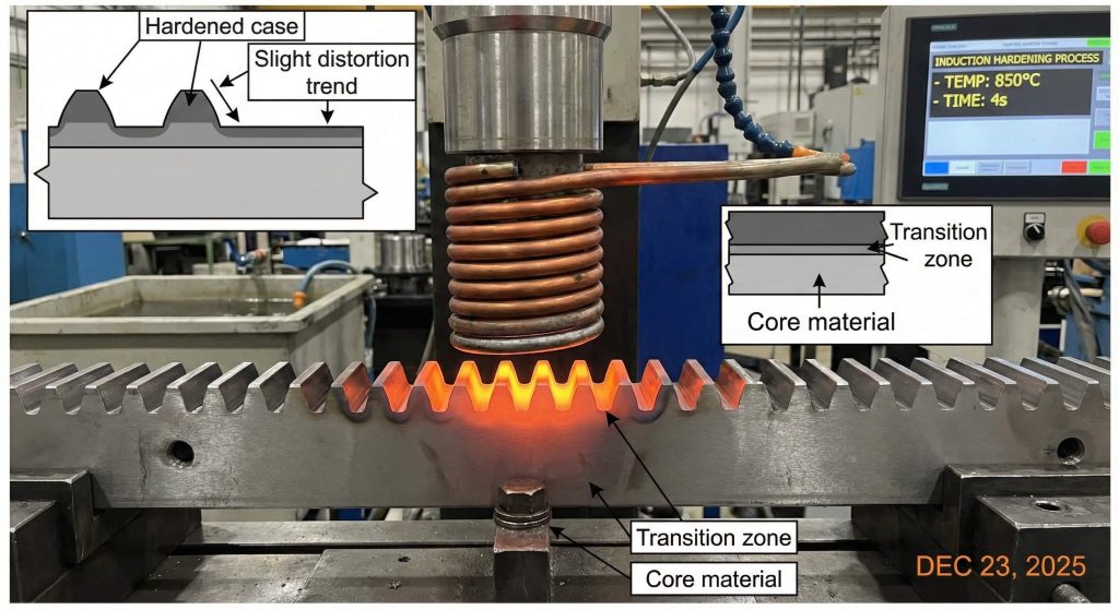
Managing Volumetric Expansion in Hardening
Volumetric expansion occurs as the molecular structure of the steel changes from pearlite to martensite during quenching. This transformation typically results in a slight increase in the overall dimensions of the rack.
Check this out:
- Case hardening depth affects internal stress.
- Core hardness provides structural toughness.
- Tempering cycles stabilize the new dimensions.
Key Takeaway: Heat treatment provides durability at the cost of immediate dimensional stability.
| Hardening Method | Depth (mm) | Distortion Risk |
|---|---|---|
| Induction | 1.0 – 3.0 | Medium |
| Carburizing | 0.5 – 1.5 | High |
Secondary grinding after hardening is the only way to ensure the rack meets high-precision motion standards.
Can tool geometry shift spur gear tolerances during gear cutting?
Tool geometry dictates the pressure angle and tooth profile, and any wear on the cutter will cause spur gear tolerances to drift over time. If a hob or milling cutter is misaligned even by a fraction of a degree, the resulting pressure angle error will cause uneven contact with the pinion. Precision engineering partners monitor tool life cycles strictly to prevent these gradual shifts in accuracy.
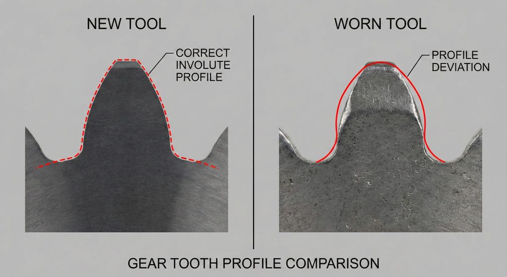
Impact of Cutter Wear on Tooth Profiles
Cutter wear changes the involute curve of the gear tooth, leading to a loss of the theoretical contact point. This results in increased noise and localized heat generation during high-speed operation.
The real kicker is:
- Tool coatings extend life but change geometry.
- Resharpening requires precise recalibration.
- Misaligned tools create “lean” in the teeth.
Key Takeaway: Sharp and aligned tooling is mandatory for maintaining consistent pitch accuracy.
| Tool Condition | Profile Deviation | Corrective Action |
|---|---|---|
| New Cutter | < 0.005mm | Standard verification |
| Worn Cutter | > 0.015mm | Immediate replacement |
Investing in high-quality cutting tools is the most cost-effective way to maintain high-volume rack production quality.
What measuring tools verify spur gear tolerances on linear racks?
Measuring tools such as Coordinate Measuring Machines (CMM) and laser interferometers verify that spur gear tolerances meet the specified engineering standards. For long racks, manual verification of straightness and cumulative pitch error is often performed using master gauges and high-precision calipers. These audits ensure that every component leaving the factory is ready for rigorous industrial service.
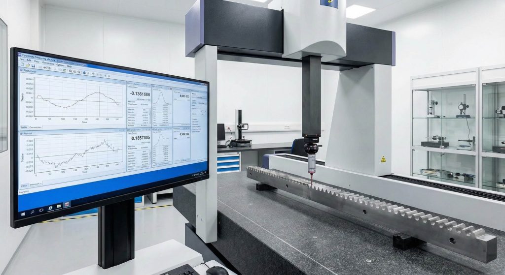
CMM Auditing for Three-Dimensional Geometry
CMM auditing allows for a complete digital recreation of the gear rack’s geometry, identifying errors in parallelism, pitch, and profile in a single pass. This provides a level of verification that manual tools cannot match.
Here is the deal:
- Probes measure tooth thickness at the pitch line.
- Scanners detect micro-deviations in surface finish.
- Digital reports provide full traceability for customers.
Key Takeaway: Advanced metrology is the final gatekeeper for gear rack quality assurance.
| Metrology Tool | Accuracy Range (µm) | Primary Use |
|---|---|---|
| CMM | 1.0 – 5.0 | Full geometry audit |
| Master Gauge | 5.0 – 10.0 | Pitch verification |
The use of high-end measuring equipment eliminates the guesswork from the gear rack manufacturing process.
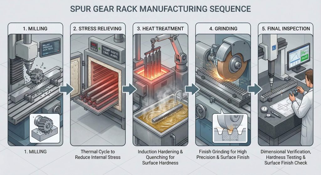
How to optimize machining for superior spur gear tolerances?
Optimizing machining for spur gear tolerances requires a strategic combination of stable feed rates, advanced cooling, and stress-relieving processes. By choosing the right sequence of milling, heat treatment, and grinding, manufacturers can produce gear racks that exceed AGMA or ISO quality standards. Precision engineering partners continuously refine these workflows to deliver the highest reliability for linear motion systems.
Balancing Material Removal and Stability
Balancing material removal involves calculating the optimal amount of steel to cut in each pass to prevent tool chatter and thermal spikes. Slow, consistent passes generally result in a much higher degree of dimensional truth.
The truth is simple:
- Flood cooling keeps the workpiece isothermal.
- Symmetric machining balances internal stresses.
- Final grinding should always follow hardening.
Key Takeaway: Optimization is a holistic approach involving material, tools, and environmental control.
| Optimization Factor | Priority | Expected Improvement |
|---|---|---|
| Thermal Control | High | 30% reduction in drift |
| Tool Alignment | Critical | 50% better profile truth |
Superior gear rack performance is the direct result of an optimized and controlled machining environment.
Frequently Asked Questions
Can I achieve ISO 6 tolerances with a milled-only gear rack?
No, ISO 6 quality typically requires precision grinding after the milling and hardening stages to reach the necessary micron-level accuracy.
What’s the best material for maintaining tolerances after heat treatment?
Medium carbon steels like S45C or alloy steels like SCM440 are preferred for their predictable volumetric expansion and stability during induction hardening.
Can a warped gear rack be fully corrected through secondary machining?
While hydraulic straightening can fix major bowing, it cannot correct localized pitch errors; only grinding the tooth faces can restore pitch integrity.
How do I calculate the required gap when joining two 1,000mm racks?
The gap should be set using a master rack or gauge that ensures the distance between the last tooth of rack A and the first tooth of rack B matches the circular pitch.
What is the difference between individual pitch error and cumulative pitch error?
Individual pitch error is the deviation between two adjacent teeth, while cumulative error is the sum of all deviations over the entire length of the rack.
Conclusion
Precision in gear rack manufacturing is not merely a matter of following a blueprint; it is the result of managing complex physical forces through expert machining. We have explored how milling, grinding, and thermal treatments interact to define the final operational envelope of your linear motion systems. By understanding these variables, you can ensure that your equipment delivers consistent, high-performance results without the threat of premature failure. For personalized engineering support or to request a quote for high-precision components, contact us today.