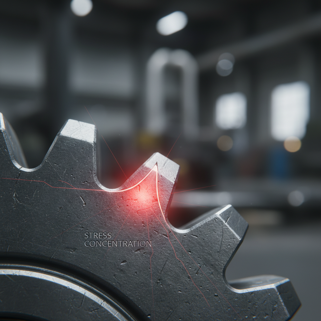
Gear Mesh Interference represents a physical collision occurring when gear tooth tips strike non-involute root sections. Sudden drivetrain failures cause massive production halts because component collisions destroy hardened steel surfaces while stalling expensive machinery. Unexpected downtime drains resources while stopping vital factory production lines. You can eliminate these collision risks through rigorous geometry optimization or mathematical verification of spur gear meshing cycles. Experts provide technical clarity for avoiding tooth contact errors during high-performance industrial operations. Achieving zero interference remains your primary goal for ensuring machinery longevity.
What causes spur gear meshing interference?
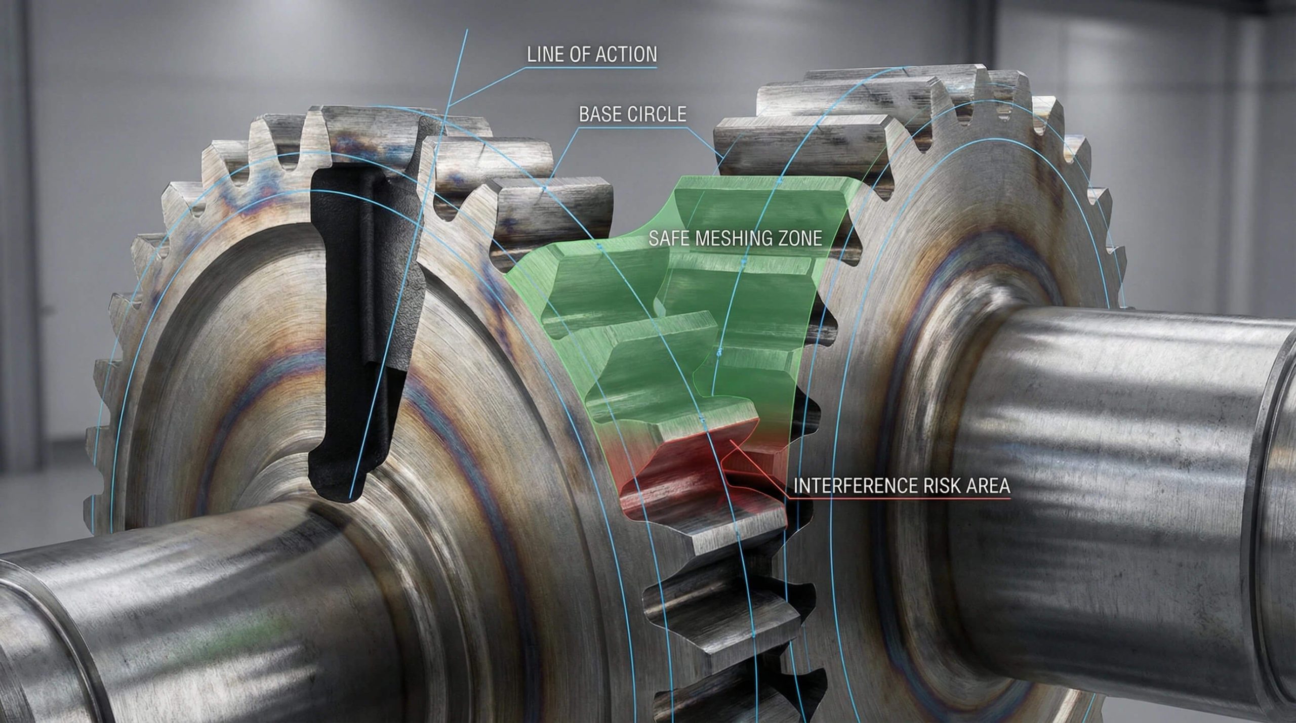
Physical collisions happen whenever gear tips strike non-involute sections during rotational spur gear meshing cycles. Every geometric failure arises because addendum circles extend beyond theoretical lines of action. Preventing abrasive wear requires you for adjusting center distances or reducing tooth heights. Maintaining conjugate motion ensures your components reach their intended life expectancy.
How do tips strike roots?
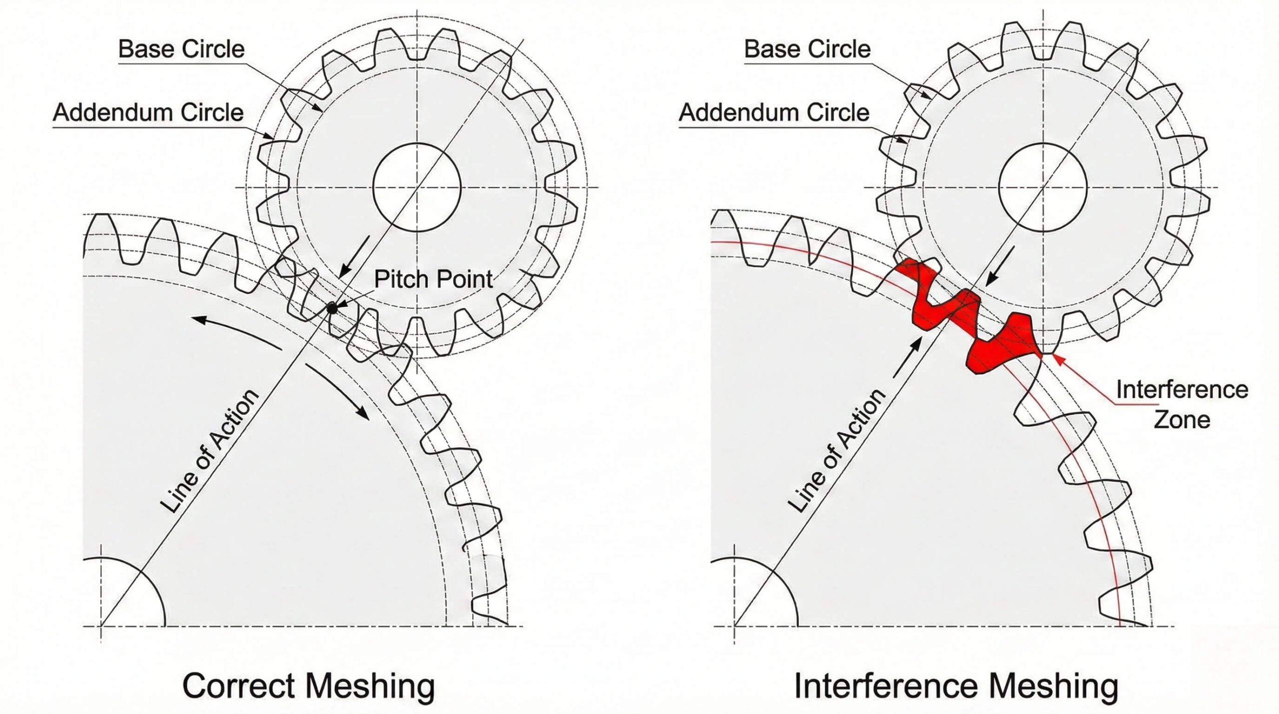
What’s the real story? Gear teeth must only make contact along that specific theoretical path. When an addendum extends past base circle tangency it creates gouging actions.
- Monitor interference points at base circle intersections.
- Verify tooth height against specific pressure angles.
- Adjust center distances for creating radial clearance.
What defines root collisions?
This is where it gets interesting… Every root area must provide enough clearance for that incoming tooth tip. If your generating tool lacks precision then resulting fillet geometry might obstruct paths.
Key Takeaway: Understanding geometric boundaries ensures that every drivetrain operates within safe limits preventing wear.
| Interference Type | Primary Cause | Risk Level |
|---|---|---|
| Tip Gouging | Long Addendum | High |
| Root Collision | Poor Fillet Shape | Critical |
| Profile Overlap | Small Base Circle | Moderate |
Rigorous assessment of these contact points prevents metal shavings from contaminating your lubrication system.
How does ratio affect spur gear meshing?
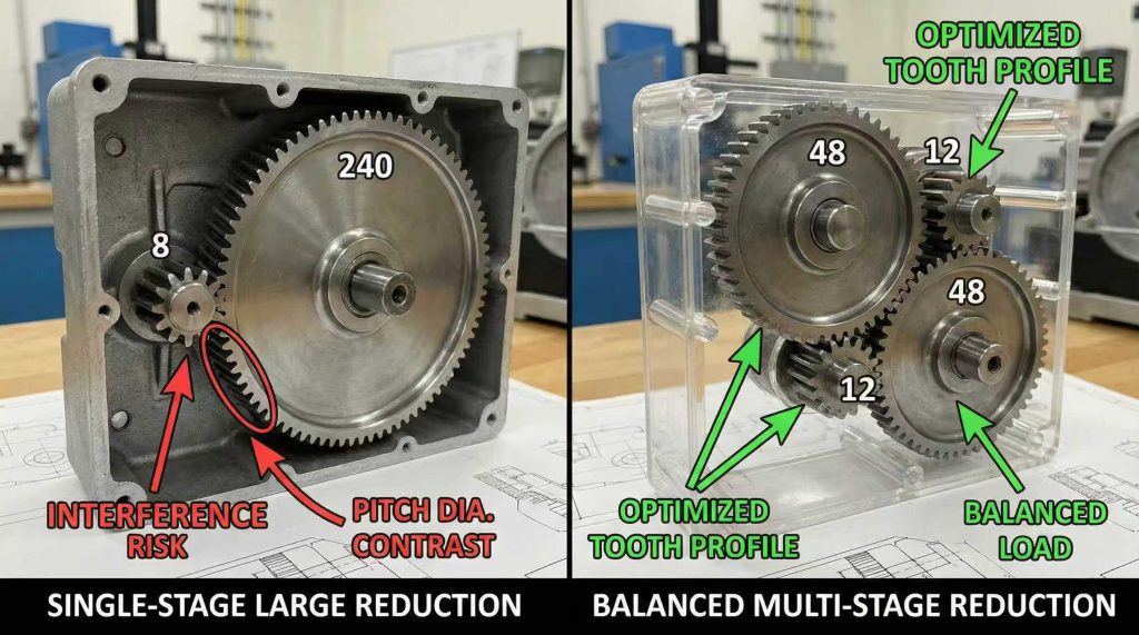
High gear ratios create geometric challenges because size disparity affects tangency during rotational spur gear meshing. Large reductions often force usage of small pinions lacking necessary tooth counts for supporting involute profiles. This mismatch causes larger gear tips for aiming toward roots of smaller pinions. Dividing aggressive ratios into multiple stages provides better balance for pitch diameters.
Why limit single stages?
Ready for the good part? Every pinion with fewer than twelve teeth will almost always experience interference when paired with large gears. This lack of surface area makes completing an involute curve difficult.
- Avoid designing pinions with extremely low counts.
- Utilize profile shifts for moving contact zones.
- Check ratios of base circles for tangency.
How can stages help?
But there is more: Dividing a 10:1 ratio into two stages significantly improves health for every mechanical component. Each gear set operates closer to 3:1 ratio which stabilizes lines of action.
Key Takeaway: Balancing gear ratios prevents geometric mismatches that lead toward root interference during operation.
| Ratio Range | Interference Risk | Best Usage |
|---|---|---|
| 1:1 to 5:1 | Minimal | General Drives |
| 6:1 to 9:1 | Moderate | Small Spaces |
| > 10:1 | Very High | Low Torque |
Proper ratio distribution ensures that each tooth handles transmitted loads without sacrificing pinion life.
Why does angle change spur gear meshing?
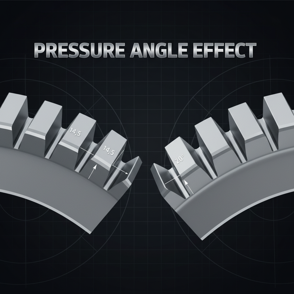
Pressure angles determine diameters for base circles where involute curves originate on every tooth during spur gear meshing. Larger angles result in smaller base circles providing longer involute portions for safe meshing. Modern industrial systems prefer twenty degrees balancing strength and interference prevention for machinery. This shift allows for smaller tooth counts on pinions without undercutting risks.
How to balance radial load?
Check this out: While higher pressure angles increase load capacity they also increase radial forces toward bearings. This trade-off requires you for evaluating housing rigidity ensuring supports handle extra forces.
- Select twenty-degree angles for heavy-duty use.
- Consider twenty-five degrees for extreme torque.
- Monitor radial load limits for bearing selection.
What impacts contact ratio?
Wait, there is more. Maintaining healthy contact ratios ensures power flows continuously without jerky motion referred to as cogging. High pressure angles tend for lowering this ratio meaning fewer teeth mesh simultaneously.
Key Takeaway: Choosing correct pressure angles acts as your primary defense against root interference.
| Pressure Angle | Strength Status | Noise Level |
|---|---|---|
| 14.5 Degrees | Low | Very Quiet |
| 20.0 Degrees | Medium | Standard |
| 25.0 Degrees | High | Increased |
Selecting appropriate angles preserves structural integrity while optimizing performance across varying torque requirements.
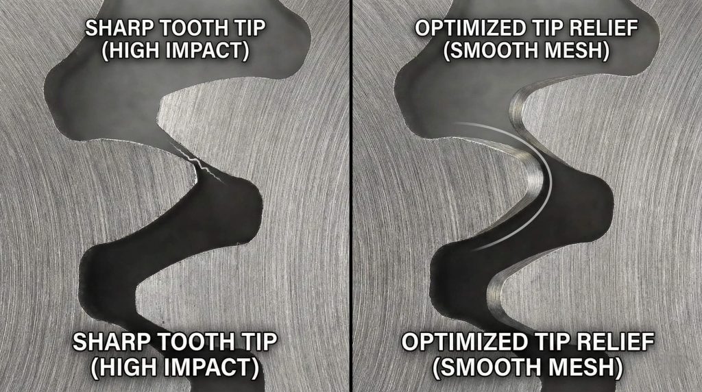
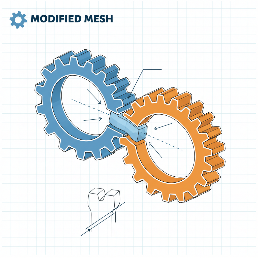
Can relief optimize spur gear meshing?
Applying radii toward every tooth tip removes sharp edges that cause gouging during spur gear meshing. This modification ensures that teeth enter mesh areas without striking flanks of partner gears. Proper tip relief acts as lead-in for rolling actions reducing impact shocks. Professionals use this technique for enhancing reliability under extreme industrial operating conditions.
How to reduce impact shock?
Think about it. Every time a new tooth enters mesh there represents a momentary impact sending vibrations through housings. Tip relief softens this transition by allowing teeth for sliding into position easily.
- Apply calculated radii toward tooth tip edges.
- Use crowning for centering loads on face.
- Minimize impact energy during high-speed rotation.
Can you over-relief teeth?
But here is the kicker. Every tip relief size must remain precisely calculated because removing too much material weakens teeth. If relief appears too large then load concentrates on smaller portions.
Key Takeaway: Tip relief constitutes a subtle modification eliminating digging actions of sharp edges during entry.
| Modification | Primary Benefit | Secondary Benefit |
|---|---|---|
| Tip Relief | Prevents Gouging | Quiet Operation |
| Tooth Crowning | Aligns Load | Reduced Stress |
| Edge Chamfer | Removes Burrs | Easier Assembly |
Calculated edge breaks facilitate smoother engagement which extends the functional life of your gear set.
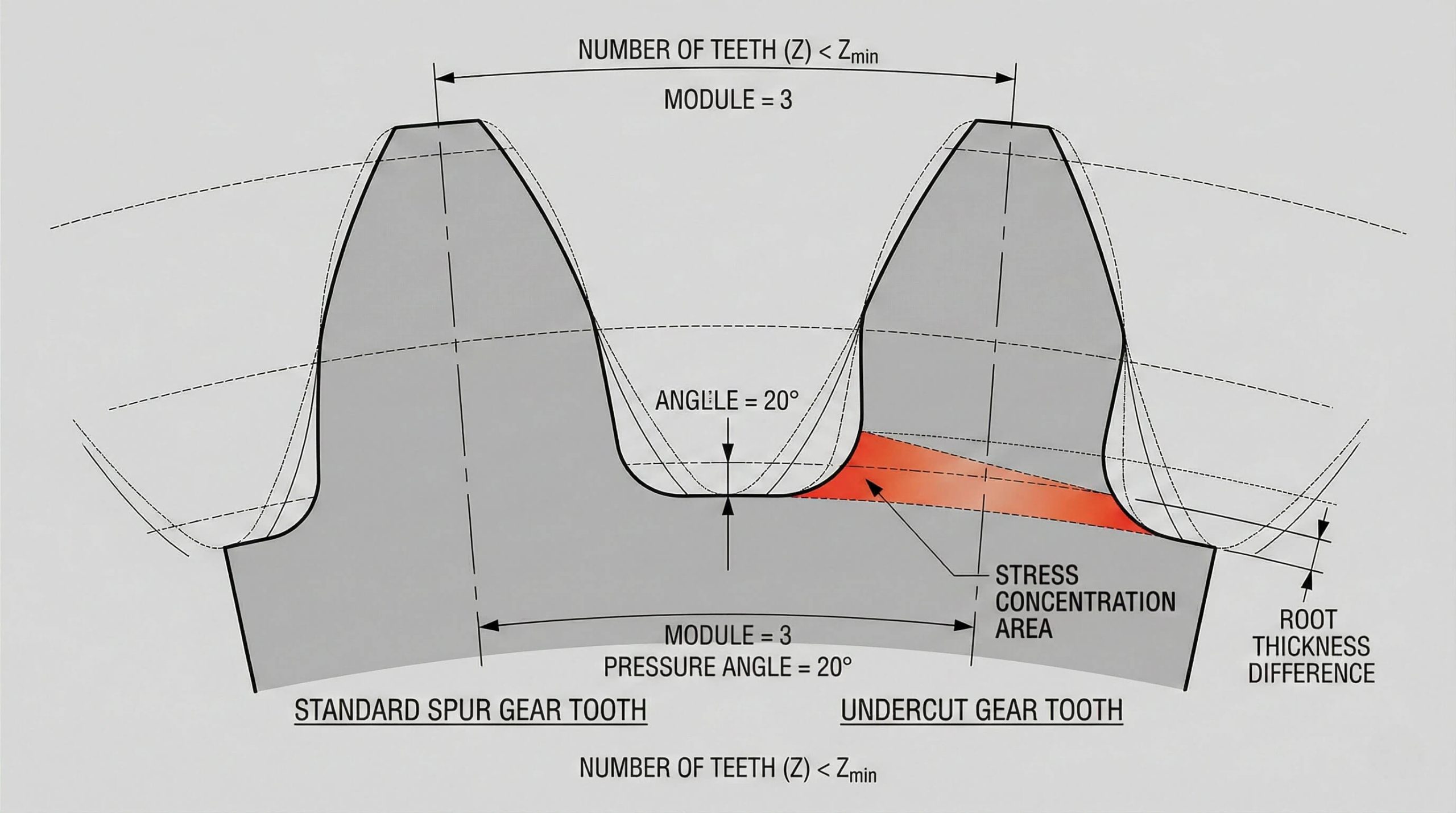
Is undercutting bad for spur gear meshing?
Undercutting occurs when cutting tools remove too much material from tooth bases hindering healthy spur gear meshing. This usually happens when pinions have too few teeth for supporting full involute profiles. Tools swing deep into roots for generating curves inadvertently carving away parts of structural bases. This creates waists that significantly weaken gears making them susceptible to snapping under shock.
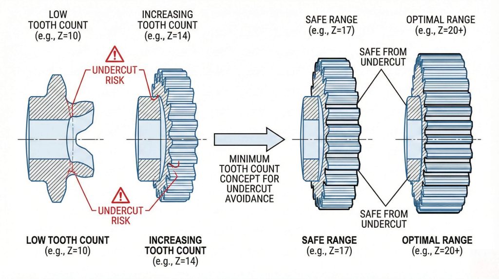
How to avoid low counts?
Now it gets interesting. Every engineer must avoid designing pinions with fewer than seventeen teeth whenever possible. While undercutting technically solves interference problems it introduces a critical point of failure at roots.
- Set minimum tooth counts of seventeen.
- Use profile shifts for avoiding undercutting.
- Check bending stress limits if undercutting remains.
Do tools cause errors?
Here comes the truth. Improper tool alignment or incorrect settings on hobbing machines lead toward accidental undercutting. If operators fail for accounting pressure angles then cutters dig too deep into fillets.
Key Takeaway: Avoiding undercutting preserves structural integrity for every gear tooth ensuring they withstand stress.
| Tooth Count | Undercut Level | Action Required |
|---|---|---|
| 10 – 12 | Critical | Redesign Gear |
| 13 – 16 | Moderate | Apply Shift |
| 17 – 20 | Minimal | Standard Check |
Maintaining thick root sections provides the necessary support for transmitting heavy industrial torque safely.
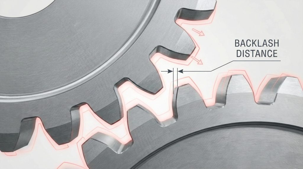
Does backlash fix spur gear meshing jams?
Backlash provides a necessary gap between non-driving sides of meshing teeth preventing jams during spur gear meshing. This clearance remains vital because it accounts for thermal expansion or minor variations in center distance. Without this gap temperature increases cause metal teeth for wedging together creating friction. Designers specify exact backlash amounts based on materials or operating environments for functionality.
Is expansion a risk?
Wait, there is more. Different materials expand at different rates meaning plastic gears require more backlash than steel systems. If gears run hot then metal grows filling available clearance potentially leading to jams.
- Calculate expansion rates for every material.
- Increase backlash for high-speed units.
- Monitor operating temperatures for avoiding seizing.
Does it stop jams?
Think about it. While excessive backlash causes noise it acts as a safety margin against manufacturing errors. If housing bores appear slightly out of position then backlash allows teeth for shifting.
Key Takeaway: Backlash constitutes a functional necessity preventing gears from destroying themselves through thermal expansion.
| Application | Backlash (mm) | Primary Goal |
|---|---|---|
| Precision Robotics | 0.03 – 0.06 | High Accuracy |
| Industrial Drives | 0.15 – 0.25 | Heat Tolerance |
| Heavy Mining | 0.40 – 0.60 | Debris Management |
Strategic clearance prevents mechanical wedging which allows your systems for operating in harsh industrial environments.
How to calculate spur gear meshing counts?
Primary formulas for interference-free design involve finding minimum tooth counts based on pressure angles during spur gear meshing. For standard twenty-degree systems seventeen teeth on pinions represents that theoretical limit for avoiding undercutting. Calculating maximum allowable addendums for gears helps define boundaries where tips might strike non-involute roots. These mathematical models must remain applied during initial design phases for success.
How to verify ratio math?
Ready for the good part? Using hunting tooth ratios ensures every tooth on pinions eventually meshes with every tooth on gears. If ratios appear as simple whole numbers then same teeth meet repeatedly causing wear.
- Use prime numbers for counts.
- Check contact frequency for recurring patterns.
- Avoid ratios forcing repetitive tooth interaction.
Why check center distance?
But there is more: Center distance constitutes a critical dimension for ensuring gears mesh at correct pitch diameters. If shafts sit too close then teeth bottom out while too far drops contact.
Key Takeaway: Precise mathematical planning eliminates guesswork in gear design ensuring tooth counts stay optimized.
| Calculation Step | Goal | Required Data |
|---|---|---|
| Min Teeth Check | Prevent Undercutting | Pressure Angle |
| Ratio Analysis | Distribute Wear | Gear Counts |
| Center Distance | Align Contact | Pitch Diameters |
Accurate modeling prevents the creation of components that cannot function within their intended mechanical assembly.
Do rack systems hit spur gear meshing bugs?
Gear racks act as gears with infinite radii creating unique interference challenges during spur gear meshing interactions. If pinions appear too small then straight edges of racks gouge bases of pinions. This collision constitutes a common problem in CNC machines where high precision remains required. Maintaining large pinion diameters or ensuring perfect alignment remains that most effective way forward.
How to align pinions?
Think about it. If pinions sit tilted relative to racks then teeth catch on edges creating stress. This end-loading leads toward rapid interference wear causing systems for jumping teeth or jamming.
- Verify parallelism with precision indicators.
- Use mounting holes for fine adjustment.
- Check for any bow in surfaces.
Can you monitor wear?
But here is the kicker. Rack systems experience localized wear if machines operate in small ranges changing tooth profiles. Once profiles appear compromised then gears run roughly potentially damaging racks requiring expensive overhauls.
Key Takeaway: Rack systems require meticulous alignment or regular inspection for preventing linear interference.
| Component | Common Failure | Prevention Strategy |
|---|---|---|
| Gear Pinion | Root Gouging | Increase Tooth Count |
| Linear Rack | Edge Scuffing | Improve Alignment |
| Interface | Debris Jamming | Install Bellows |
Frequent inspection of these linear interfaces ensures your precision positioning systems maintain their accuracy over time.
Which metal boosts spur gear meshing life?
Hardened steel gears resist abrasive wear or gouging better than soft materials during spur gear meshing cycles. Processes like carburizing create hard outer cases while keeping cores tough enough for absorbing impact. Choosing correct material compatibility ensures that pinions or gears do not eat each other through galling. This strategy remains essential for maintaining geometry integrity and preventing catastrophic tooth failure.
Which hardness is best?
What’s the real story? Hardness of tooth surfaces determines how well they withstand pressure of minor interference points. If gears appear too soft then they quickly lose shape leading toward breakdowns in motion.
- Use carburized steel for torque.
- Ensure cores remain ductile for impact.
- Monitor case depth during heat-treat.
Are materials compatible?
Ready for the good part? Pairing correct materials remains essential because using identical hardness levels leads toward galling. Typically smaller pinions should stay slightly harder than larger gears for balancing wear rates.
Key Takeaway: Correct material selection acts as a safety net ensuring gear surfaces remain intact.
| Material | Hardness (HRC) | Key Characteristic |
|---|---|---|
| Alloy Steel | 55 – 60 | High Wear Resist |
| Tool Steel | 60 – 64 | Extreme Hardness |
| Bronze Metal | 15 – 25 | Self-Lubricating |
High-quality alloys provide the structural durability needed for sustaining high-performance transmission throughout their service life.
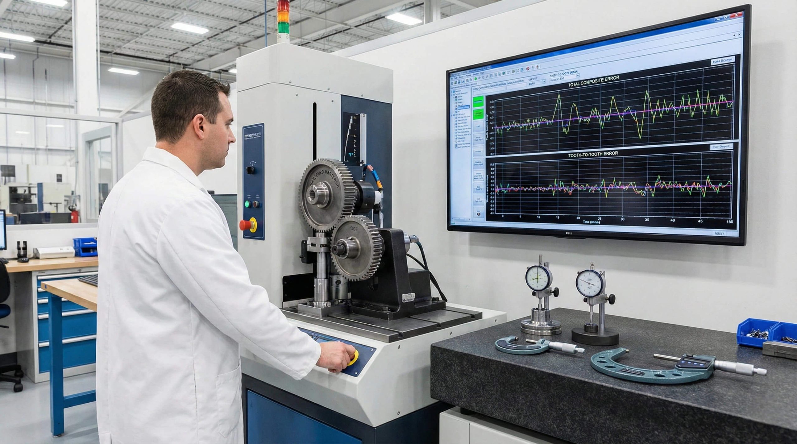
How to inspect spur gear meshing quality?
Precision inspection requires specialized tools for verifying that tooth profiles match theoretical designs for spur gear meshing. Machines measure deviations from ideal curves with sub-micron accuracy ensuring no interference points exist. Lead checks remain performed for ensuring that teeth stay straight across face widths preventing failure. Quality control acts as that final gatekeeper preventing faulty components from reaching your field.
How to use roll tests?
This is where it gets interesting… Functional roll testing involves meshing production gears with precision master gears measuring variation. This test reveals total composite errors and identifies nicks missed during single-point measurement processes.
- Perform roll tests for error detection.
- Use certified master gears for precision.
- Document center distance variation for logs.
What are the standards?
Wait, there is more. International standards define allowable errors for different gear classes helping you for choosing precision. Class 12 gears appear much more accurate than Class 6 so choices must reflect needs.
Key Takeaway: Rigorous quality control remains a final gatekeeper preventing interference-prone parts from entering machinery.
| Metric | Measurement Tool | Target Tolerance |
|---|---|---|
| Involute Error | Profile Tester | +/- 0.008 mm |
| Lead Error | Lead Tester | +/- 0.012 mm |
| Pitch Error | Gear Micrometer | +/- 0.005 mm |
Certifying your components ensures they perform reliably within specified operating parameters without causing unexpected system failures.
Conclusion
Precision in gear geometry represents a fundamental requirement for operational safety or long-term profitability in industrial environments. We analyzed how tooth counts or pressure angles interact for creation of stable mechanical systems. Our specialists stand at the forefront of high-performance transmission design ensuring every component meets rigorous standards. If your engineering team faces complex meshing challenges or requires custom components, contact us today.
FAQ
Q1: Can I use a pinion with fewer than 12 teeth safely?
No, you should avoid this because fewer than 12 teeth almost always lead toward critical undercutting. This removes vital material from the root which compromises the structural integrity of your gear set.
Q2: What’s the best way to detect interference without expensive machines?
A manual “blueing” test represents the best method because it reveals contact patterns through dye displacement. You coat the teeth and rotate them for identifying where gouging or abrasive wear occurs.
Q3: Can I mix different pressure angles in the same gear set?
No, you must never mix pressure angles because the teeth will not follow a shared line of action. This mismatch leads to immediate mechanical jamming and potential destruction of the tooth profiles.
Q4: How do I know if thermal expansion is causing my gear jams?
You monitor the operating temperature because seizing that occurs only after the system warms up indicates insufficient backlash. Metal growth fills available clearance which forces the teeth to wedge together during rotation.
Q5: How do I know if tip relief is necessary for my application?
Tip relief becomes necessary whenever you observe bright scuff marks at the start of the tooth engagement zone. These marks signal that sharp edges are digging into the mating flank rather than rolling smoothly.