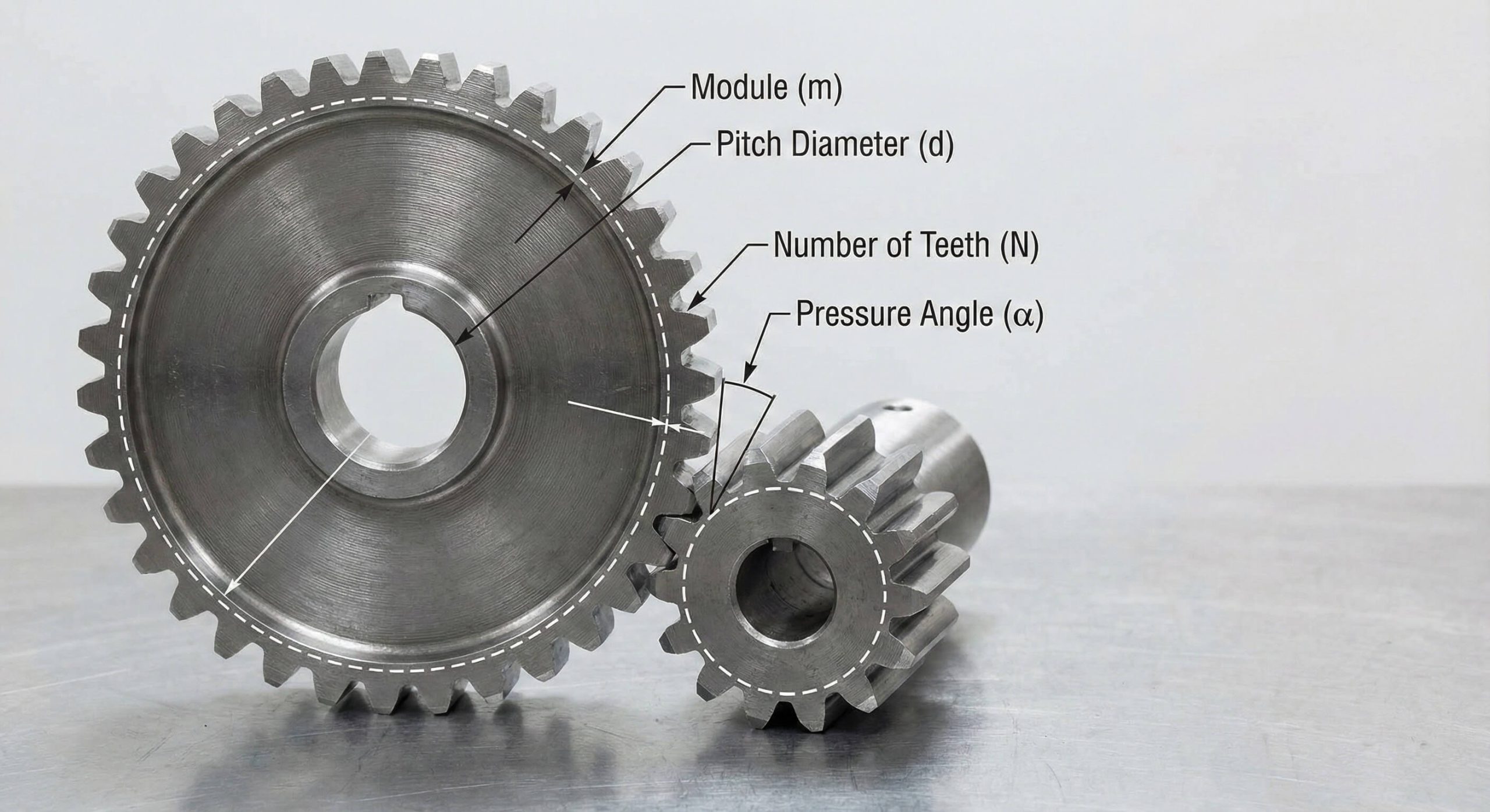
Spur gear tooth geometry involves specific dimensional parameters like module and pitch diameter that define how power transmission components interact. Engineers frequently encounter catastrophic system failures when mismatched parts undergo high stress or speed. These technical errors lead to expensive downtime, yet finding clear guidance on gear standards remains difficult. Mastering these concepts ensures that spur gear tooth designs operate with maximum reliability and precision. You can guarantee that your drivetrain systems remain functional by following these foundational geometric principles.
What is the primary function of a spur gear tooth?
The primary function of a spur gear tooth is to facilitate the smooth transfer of torque between parallel shafts while maintaining a constant velocity ratio. This specific mechanical interaction allows machinery to handle industrial loads without fracturing under heavy stress or high speeds. High-speed applications require precise geometry to prevent vibration or premature bearing failure during continuous operation. You must ensure the profile is optimized for the intended load to avoid surface pitting.
Mechanical Mesh Reliability
Strength in a gearset relies on the ability of each tooth to withstand bending forces during engagement across the pitch point.
This is where it gets interesting.
- Constant velocity maintenance
- Torque transmission efficiency
- Load sharing capabilities
Key Takeaway: Correct geometry guarantees nearly 98 percent energy transfer efficiency during operation while reducing heat buildup.
| Parameter | Role | Benefit |
|---|---|---|
| Surface | Contact zone | Friction reduction |
| Root | Strength base | Stress resistance |
| Tip | Entry point | Smooth engagement |
Use this table to identify how different zones support functional performance during machine operation to prevent component failure.
How does the pitch diameter define a spur gear tooth profile?
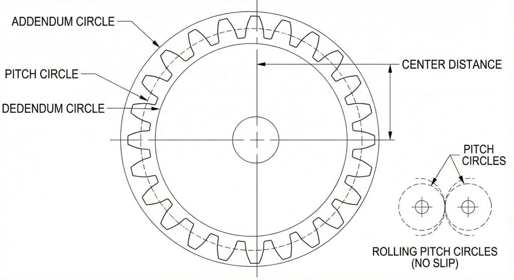
The pitch diameter defines a spur gear tooth profile by acting as the diameter of an invisible reference cylinder that passes through the approximate midpoint of every tooth. You can think of this as the theoretical circle where two wheels roll together without any slipping or friction. Accurate alignment of these circles prevents excessive backlash which quickly destroys expensive internal components. This specific dimension determines both speed and torque characteristics for your entire drivetrain assembly.
Reference Circle Utility
Because the pitch diameter dictates the mating envelope, it remains the primary reference for calculating center distances between shafts.
But here’s the kicker.
- Defines pressure angle
- Sets tooth thickness
- Establishes reference line
Key Takeaway: Pitch diameter is the foundation for all geometric consistency and is used to calculate every other gear dimension.
| Metric | Definition | Significance |
|---|---|---|
| Pitch Circle | Theoretical roll line | Mating boundary |
| Pitch Diameter | Reference measurement | Sizing basis |
| Pitch Point | Contact intersection | Force location |
Engineers must start with this value when drafting gear layouts to guarantee part compatibility and proper shaft alignment.
Why is the module necessary for every spur gear tooth?
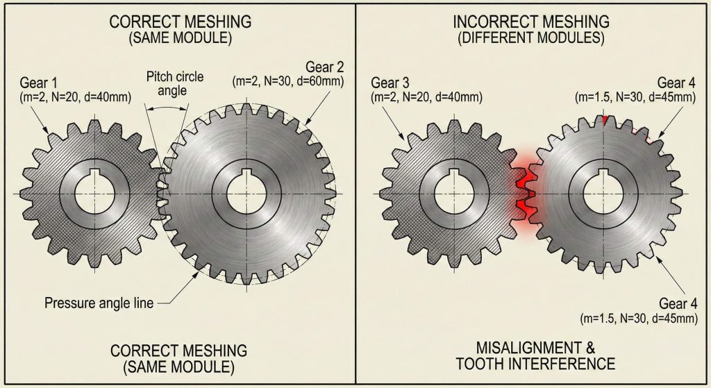
The module is necessary for every spur gear tooth because it acts as a standardized metric defining the unit size of a tooth relative to its diameter. It simplifies matching parts from different suppliers because components with identical modules will always mesh properly regardless of their total size. You calculate this value by dividing the pitch diameter by the total tooth count present on the gear body. Standardization guarantees that tooth thickness and spacing remain proportional to the overall gear diameter.
Standardizing Gear Sizes
Global design languages rely on the module system to ensure that replacement parts fit existing machinery without modification.
You might be wondering.
- Matching unit sizes
- Simplified procurement
- Global design language
Key Takeaway: Matching modules is the first rule for guaranteeing functional gear meshing and preventing mechanical interference.
| Symbol | Meaning | Formula |
|---|---|---|
| m | Module | d / N |
| d | Pitch Diameter | m * N |
| N | Tooth Count | d / m |
Use these formulas to verify that your selected pinion will interface correctly with the main gear body before assembly.
What are the geometric zones of a spur gear tooth?
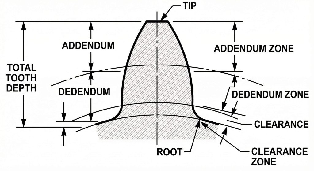
The geometric zones of a spur gear tooth include the addendum and dedendum which define the total depth and engagement characteristics. The addendum extends outward from the pitch circle to the outer tip of the tooth structure. The dedendum represents the portion extending inward from that same reference line toward the root diameter. Total depth must accommodate the mating component without physical interference during full engagement cycles.
Functional Depth Parameters
Proper clearance at the bottom of the tooth space prevents the tip of the mating gear from hitting the root.
Here’s the deal.
- Addendum height
- Dedendum depth
- Root clearance gap
Key Takeaway: Maintaining correct working depth prevents binding while securing maximum surface contact for load distribution.
| Zone | Location | Function |
|---|---|---|
| Addendum | Above pitch | Engagement length |
| Dedendum | Below pitch | Root clearance |
| Root | Base area | Load support |
This structure allows for lubrication flow and accommodates thermal expansion during continuous high-temperature operation in industrial environments.
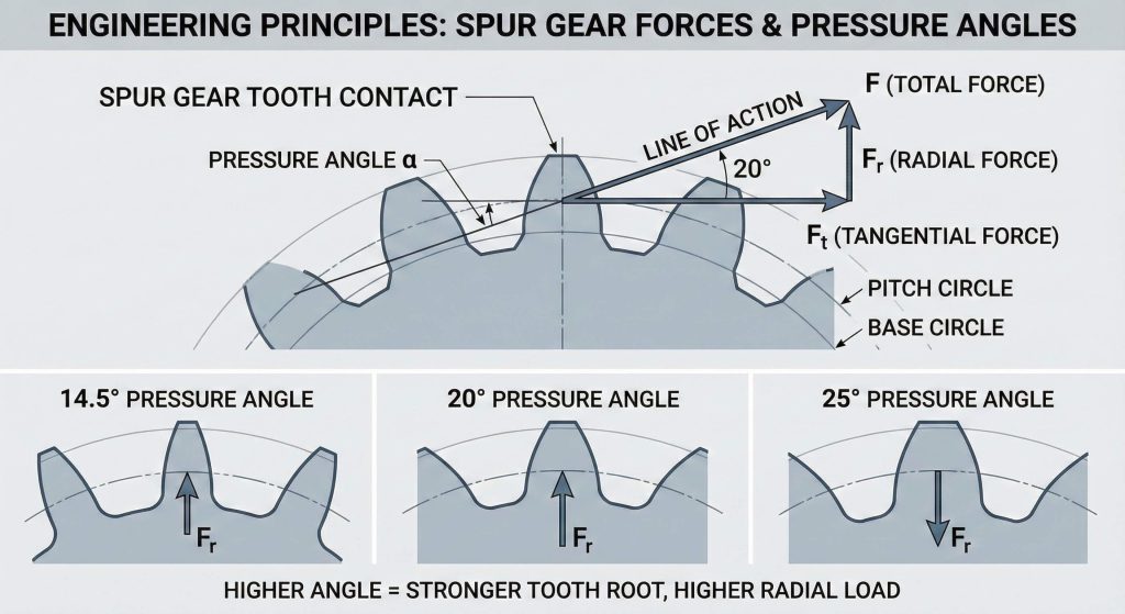
How does the pressure angle influence every spur gear tooth?
The pressure angle influences every spur gear tooth by defining the direction of the force acting on the surface as it enters the mesh. Most industrial applications utilize a 20-degree standard because it offers a superior balance between strength and smooth operation. A steeper angle creates a thicker base which significantly increases resistance to bending loads and stress fractures. However, higher angles also increase radial forces on the bearings which might require more robust support structures.
Load Distribution Factors
The shape of the surface profile changes based on this angle, affecting how the flanks slide against each other.
Think about it.
- Common 20-degree standard
- 14.5-degree legacy use
- Impact on noise levels
Key Takeaway: Selecting the right pressure angle balances torque capacity against the mechanical constraints of the housing.
| Angle | Strength | Noise Level | Application |
|---|---|---|---|
| 14.5° | Lower | Quiet | Legacy sets |
| 20.0° | High | Moderate | General use |
| 25.0° | Highest | Louder | Heavy duty |
Manufacturers standardize these angles to guarantee that replacement parts fit existing machinery without the need for complex modifications.
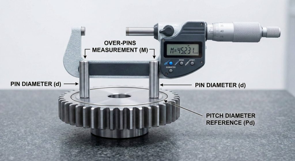
Can you measure the pitch diameter of a spur gear tooth directly?
You cannot measure the pitch diameter of a spur gear tooth directly because it represents a theoretical line in space. You must use indirect methods to verify the accuracy of your gear components during the inspection process. The most reliable technique involves placing precision dowel pins between the teeth and measuring the total distance over them. You then subtract the pin diameter from the total measurement to accurately estimate the reference circle.
Precision Inspection Methods
Standard calipers alone often fail to align with the true pitch point on the curved flank surface.
What’s the real story?
- Over-pins measurement
- Micrometer verification
- Pin size charts
Key Takeaway: Indirect measurement accounts for variations in thickness and delivers repeatable quality control data for manufacturers.
| Tool | Usage | Accuracy |
|---|---|---|
| Dowel Pin | Reference | High |
| Caliper | Rough check | Low |
| Micrometer | Total size | High |
High-precision manufacturing requires these checks to guarantee that parts meet required tolerances for high-speed operation and longevity.
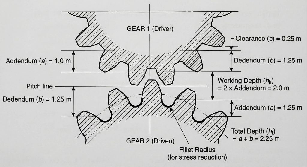
What defines the working depth for every spur gear tooth?
Working depth for every spur gear tooth refers to the distance a tooth extends into the space of the mating gear during full engagement. This value is typically equal to twice the addendum and specifically excludes the clearance gap at the root. Proper depth prevents gears from binding while securing maximum surface contact for efficient load distribution. The root fillet radius at the base is another critical feature that reduces destructive stress concentrations.
Engagement and Clearance
Smooth transitions from the flank to the root prevent cracks from forming under heavy cyclic loading conditions.
Ready for the good part?
- Total depth calculation
- Working depth limit
- Fillet radius role
Key Takeaway: A well-designed profile leaves enough room for lubricant to escape the mesh zone without causing pressure spikes.
| Feature | Value | Goal |
|---|---|---|
| Addendum | 1.0 * m | Reach |
| Dedendum | 1.25 * m | Depth |
| Clearance | 0.25 * m | Gap |
Designers must carefully calculate these clearances to allow for oil film thickness and common manufacturing deviations in the shop.
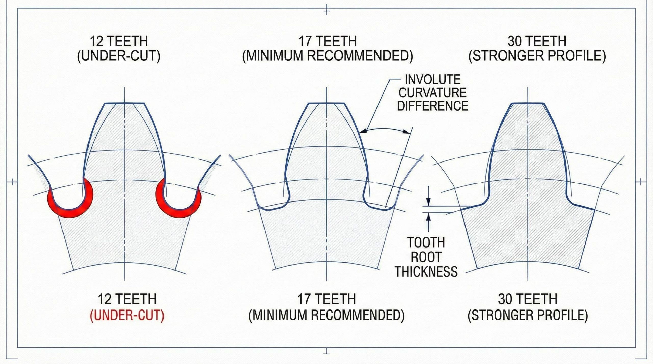
How does the tooth count affect spur gear tooth curvature?
The tooth count affects spur gear tooth curvature by determining the final physical size and the shape of the involute profile. As the count decreases, the profile becomes more curved which can lead to a phenomenon known as undercutting. Undercutting removes material from the base which severely weakens the structural integrity of the gear component. Most designers maintain a minimum of 17 teeth for standard 20-degree pressure angle components to avoid these issues.
Geometric Limitations
If your design requires a smaller pinion, you might need to use profile shifting to strengthen the base.
This is where it gets interesting.
- Minimum tooth limits
- Profile shift usage
- Undercutting risks
Key Takeaway: Precision in spacing is what separates high-quality components from cheap alternatives that cause vibration and noise.
| Count | Shape | Strength |
|---|---|---|
| Low (<12) | Highly curved | Low |
| Med (17-30) | Standard | High |
| High (50+) | Flatter | Very High |
The relationship between the tooth count and the pitch diameter is linear for any constant module used in the design.
Which materials are best for every spur gear tooth?
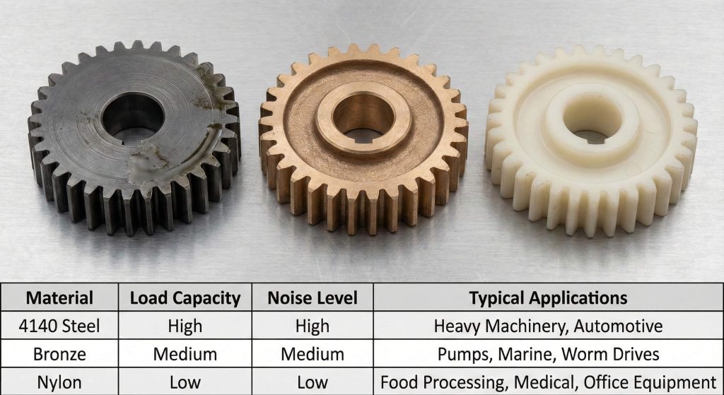
High-strength alloy steels like 4140 are the best materials for every spur gear tooth because they respond well to heat treatment. Selecting the right material depends on specific torque requirements and the environmental conditions of your application. Engineering polymers like nylon are excellent for low-load applications where noise reduction and weight are your primary concerns. You must match the material hardness to the operating environment to prevent premature wear from corrosion.
Material Performance Choices
Engineering polymers allow the profile to flex slightly which helps distribute loads and dampen harmful vibrations.
You might be wondering.
- Alloy steel strength
- Nylon noise reduction
- Surface hardening needs
Key Takeaway: Surface hardening techniques like nitriding create a wear-resistant skin while maintaining a tough, shock-absorbing core.
| Material | Benefit | Load Capacity |
|---|---|---|
| 4140 Steel | Toughness | High |
| Nylon | Quiet | Low |
| Bronze | Low friction | Medium |
Choosing a material that matches the operating environment prevents premature wear from corrosion or abrasive particles entering the gearbox.
Why is lubrication necessary for every spur gear tooth?
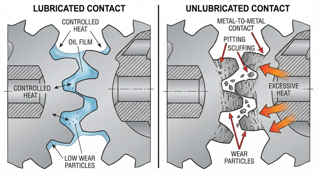
Lubrication is necessary for every spur gear tooth because even the most perfectly designed profile will fail rapidly without an adequate protective film. Lubricants create a thin layer that prevents metal-to-metal contact as the flank slides into the mesh. This sliding action generates significant heat which must be carried away to prevent thermal distortion of the gear teeth. High-pressure additives are often required for components operating under heavy loads or extreme temperature conditions.
Friction and Wear Reduction
Choosing the correct viscosity guarantees that the lubricant stays on the surface without being flung off at high speeds.
But here’s the kicker.
- Film thickness role
- Heat dissipation
- Viscosity selection
Key Takeaway: Regular maintenance and oil analysis can detect early signs of wear by identifying metallic particles in the fluid.
| Lubricant | Benefit | Condition |
|---|---|---|
| Grease | Stays on gear | Low speed |
| Mineral Oil | Cooling | High speed |
| Synthetic | Temp range | Extreme |
Protecting your investment in high-quality gears requires a consistent lubrication strategy tailored to your specific operating speeds and loads.
Conclusion
We have explored the fundamental parameters that govern the design and function of the gear profile in modern industrial systems. From the invisible pitch diameter to the standardized gear module, these dimensions guarantee that power transmission remains efficient. Every calculation regarding tooth thickness or pressure angle directly impacts the lifespan of your mechanical assembly. By prioritizing compatible modules and robust materials, you can eliminate the risk of premature failure. If you require specialized assistance with your drivetrain components, please contact us today.
Frequently Asked Questions
Q1: Can I use gears with different modules in the same assembly?
No, you cannot mate gears with different modules because the tooth size and spacing will not align for proper engagement.
Q2: What’s the best way to calculate the outer diameter of a gear?
The best way is to calculate the outer diameter by adding two module units to the pitch diameter of the gear body.
Q3: How do I know if I have the correct pressure angle?
You know you have the correct angle if the gears run smoothly without binding and the base of the tooth shows no undercutting.
Q4: Where should I measure the tooth thickness?
You should measure the tooth thickness along the pitch circle arc to guarantee accurate backlash calculations and fitment.
Q5: Is there a minimum number of teeth required to avoid undercutting?
Yes, you should maintain a minimum of 17 teeth for standard 20-degree gears to avoid weakening the base of the tooth profile.