Introduction
Inefficiency in power transmission is the silent killer of industrial machinery performance, capable of turning a profitable production line into a maintenance nightmare. You design a system specifically for high torque and compact positioning, but if the worm gear drive isn’t calibrated with absolute precision, you end up with a gearbox that acts more like an industrial heater than a motion transfer device. Many engineers and procurement officers struggle with the delicate, high-stakes balance between achieving the necessary speed reduction and maintaining thermal stability, often realizing too late that their theoretical calculations don’t hold up under real-world load conditions.
This miscalculation leads to catastrophic risks: stripped bronze teeth, seized shafts caused by unchecked thermal expansion, and dangerous, unexpected back-driving in critical hoisting applications. These aren’t just mechanical failures; they are production stoppages that bleed revenue and compromise worker safety. By mastering the specific nuances of the gear ratio of a worm gear, you transform a potential failure point into a reliable, high-torque asset. At Yantong Tech, we see these issues daily, and we know that precise calculation combined with superior manufacturing is the only way to ensure your machinery operates safely and efficiently.
1. Understanding the Basics of Gear Ratio of a Worm Gear
The fundamental architecture of a worm drive is distinct from any other gear set, requiring a unique approach to understanding its mechanical advantage. Before you can calculate ratios, you must understand the geometry that dictates how power is transferred from a steel shaft to a bronze wheel.
What distinguishes worm gearing from other types?
Worm gears function differently than standard spur or helical gears because they rely almost entirely on sliding contact rather than rolling contact. This unique geometry allows for massive speed reductions in a single stage—typically ranging from 5:1 up to 100:1—often replacing complex, bulky multi-stage gearboxes with a compact unit. However, this sliding action introduces high friction, making the understanding of the ratio critical for predicting heat generation.
- Compact Reduction: Achieves high ratios in limited spaces.
- Sliding Friction: Generates significantly more heat than rolling gears.
- Orthogonal Transfer: Transmits power at a 90-degree angle.
Here is the catch: Because the transmission relies on sliding, the surface finish and material quality are paramount. If you misunderstand the ratio’s effect on sliding velocity, you risk rapid wear regardless of lubrication quality.
How are the primary components defined?
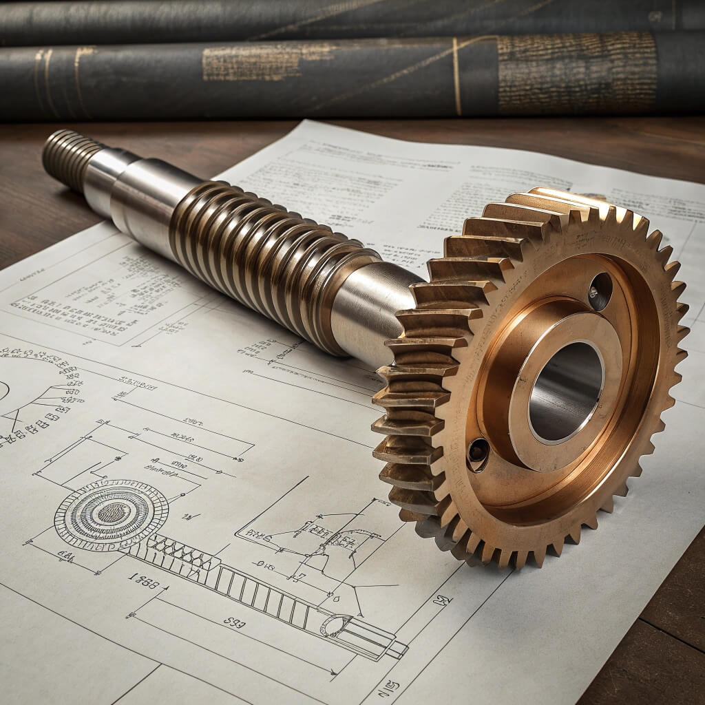
The system consists of two main parts: the worm (the screw-like input shaft) and the worm wheel (the driven bronze gear). Unlike standard gears where you simply count teeth on both the input and output, the worm generally has “starts” or threads rather than teeth. This distinction is crucial. Misidentifying a 2-start worm as a single-start worm will double your output speed and halve your torque, leading to immediate system overload.
- The Worm: The driver, typically steel, resembling a threaded screw.
- The Wheel: The driven component, typically bronze, with concave teeth.
- Starts: The number of independent thread helixes on the worm shaft.
Think about it: You are essentially threading a nut (the wheel) onto a screw (the worm), but the nut is constrained to rotate rather than move axially.
Key Takeaway
You must view the worm gear set as a screw and nut system rather than two mating gears. The ratio is not just about speed; it dictates the mechanical advantage and the physical sliding velocity between the steel shaft and the bronze wheel.
Table 1: Key Components Affecting Ratio Calculation
| Component | Definition | Role in Calculation |
|---|---|---|
| Worm Starts ($Z_1$) | Number of independent threads on the shaft. | Acts as the “number of teeth” for the input. |
| Wheel Teeth ($Z_2$) | Number of teeth on the driven gear. | The numerator in the ratio formula. |
| Lead Angle | The angle of the thread inclination. | Affects efficiency and self-locking, derived from ratio. |
| Axial Pitch | Distance between threads. | Ensures proper meshing geometry. |
Understanding the physical anatomy of the gear set is the absolute prerequisite to any mathematical calculation.
2. The Formula for Calculating Worm Gear Ratios
Once you have identified the physical components, applying the math is straightforward, yet it remains the most common source of error in replacement orders. Precision in identifying the variables is far more difficult than the division itself.
What is the standard calculation formula?
The math behind calculating worm gear ratios is deceptive in its simplicity but unforgiving if variables are wrong. The formula is the number of teeth on the worm wheel divided by the number of starts on the worm shaft. This linear relationship defines the mechanical advantage of the system.
- $Ratio (i) = \frac{N_{gear}}{N_{worm}}$
- $N_{gear}$ = Number of teeth on the worm wheel.
- $N_{worm}$ = Number of starts (threads) on the worm.
Why does this matter? A simple counting error on the “starts” can result in a 50% or 100% deviation in output speed, rendering the machine useless or dangerous.
How do you correctly identify the number of starts?
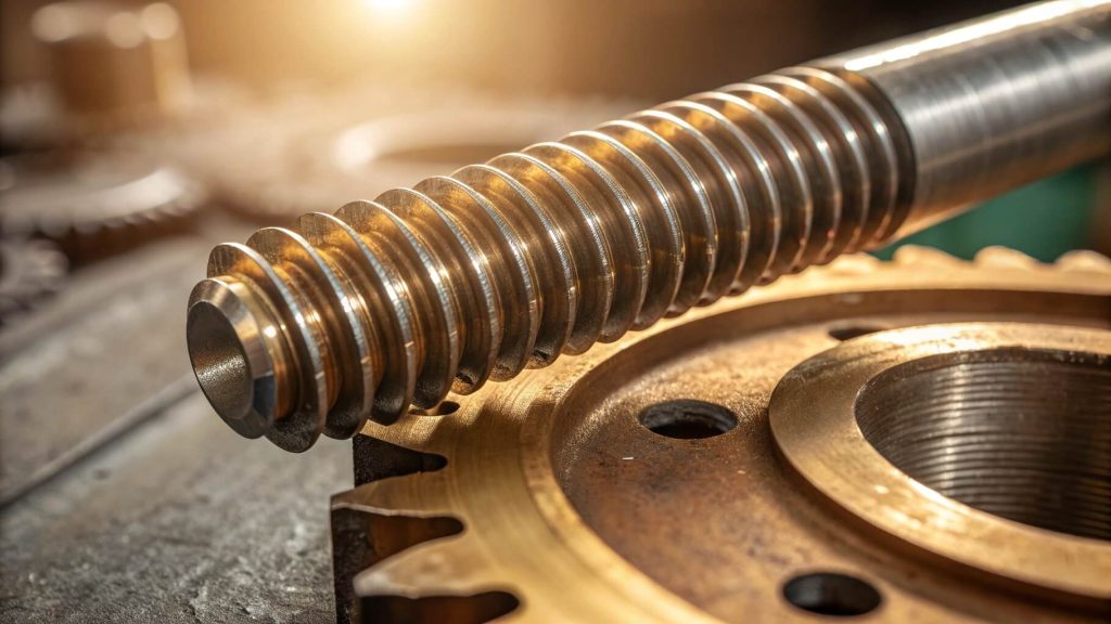
Counting teeth on the bronze wheel is easy, but counting starts on the worm shaft trips up many engineers. A single-start worm looks like a continuous screw; one full revolution advances the gear by one tooth. Look closely at the end of the shaft. If you see two thread ends starting 180 degrees apart, it is a 2-start worm; if you see four ends 90 degrees apart, it is a 4-start worm.
- Single Start: One continuous thread (Ratio = Teeth / 1).
- Double Start: Two distinct threads (Ratio = Teeth / 2).
- Quad Start: Four distinct threads (Ratio = Teeth / 4).
Here is the reality: Most people try to trace the thread visually along the shaft, but the helix angle creates an optical illusion that makes accurate counting difficult without checking the shaft end.
Key Takeaway
Always verify the number of starts physically if you are reverse-engineering a component. Relying on assumptions or visual estimation of the helix angle without counting the thread starts at the shaft end is a primary cause of ordering incorrect replacement parts.
Pro Tip: Use a felt-tip marker to mark one thread at the end of the worm shaft face. Trace it with your finger for one full revolution (360 degrees). If you arrive at the next adjacent thread, it is a multi-start worm. If you arrive further down the same thread valley, check the end face again to count the start points.
Mathematical accuracy is useless if the physical observation of the input variables is flawed.
3. Worm Gear Ratio Selection Factors
Selecting a ratio is not merely about matching an output speed; it is about balancing torque multiplication against the physical limitations of the materials involved. This decision dictates the lifespan and duty cycle of your machinery.
How does torque requirement dictate the ratio?
Torque multiplication is the main reason you choose a worm gear over other transmission types. A higher gear ratio of a worm gear results in higher output torque but significantly lower speed. For example, a 60:1 ratio offers immense lifting power suitable for hoists, whereas a 5:1 ratio is used for timing or slight speed adjustments where torque is secondary.
- High Torque: Requires high ratios (40:1 to 80:1).
- High Speed: Requires low ratios (5:1 to 15:1).
- Balanced: Medium ratios (20:1 to 30:1) for general conveyors.
Consider this: As the ratio increases, the gear set acts as a more powerful lever, allowing a smaller motor to move a heavier load, provided the speed sacrifice is acceptable.
What impact does input speed have?
You cannot simply select the highest ratio to get the most torque without considering the input speed limits. High ratios combined with high input speeds (e.g., 3000 RPM) result in excessive sliding velocity. Here is the danger zone. If the sliding velocity exceeds the lubricant’s film strength capabilities, you will experience metal-to-metal contact and rapid failure of the bronze wheel.
- Sliding Velocity: Increases with input speed and diameter.
- Film Strength: Oil must separate metal surfaces under pressure.
- Scuffing: The result of velocity exceeding lubrication limits.
Bottom line: A ratio that works perfectly at 1400 RPM might fail catastrophically at 3000 RPM due to the exponential increase in frictional heat generation.
Key Takeaway
Selection is a trade-off. You trade output speed for torque, but you also trade thermal capacity. A high-ratio gearbox must be sized larger or cooled aggressively if the input speed is high, regardless of the theoretical torque calculation.
Table 2: Ratio vs. Application Suitability
| Ratio Range | Typical Application | Torque Char. | Speed Char. | Efficiency Risk |
|---|---|---|---|---|
| Low (5:1 – 15:1) | Conveyors, Timing | Moderate | High | Low |
| Medium (20:1 – 40:1) | Mixers, Packaging | High | Moderate | Medium |
| High (50:1 – 80:1) | Hoists, Lifts | Very High | Low | High |
| Extreme (>100:1) | Rotary Tables | Max | Very Low | Very High |
Balancing the mechanical advantage against the physical limits of the materials is the essence of engineering selection.
4. Efficiency and Heat in High Gear Ratio of a Worm Gear
The most overlooked aspect of worm gear design is the efficiency penalty that comes with high reduction ratios. Unlike other gears, where efficiency is constant, worm gear efficiency fluctuates wildly based on the ratio.
Why does efficiency drop as ratio increases?
There is a direct, inverse relationship between the gear ratio and efficiency. High ratios (like 60:1 or 80:1) imply a small lead angle on the worm threads. A small lead angle means the gear relies more on sliding friction than rolling action to transmit power. This friction converts a significant portion of your input motor power directly into heat rather than output torque.
- Low Ratios: High lead angle, high efficiency (85-90%).
- High Ratios: Low lead angle, low efficiency (50-70%).
- Energy Loss: Dissipated entirely as heat through the casing.
Why is this critical? If you assume 95% efficiency for a 60:1 worm gear, your motor will be undersized, and your gearbox will overheat within minutes of operation.
How can you mitigate thermal failure?
To run a high-ratio worm gear successfully, you must account for the “thermal rating” of the gearbox, which is often lower than the “mechanical rating.” Physics does not negotiate. You must use high-grade synthetic lubricants and ensure the worm wheel is manufactured from high-quality centrifugally cast bronze (like CuSn12) to withstand the thermal stress.
- Material Choice: CuSn12 Nickel Bronze resists heat better than standard Aluminum Bronze.
- Lubrication: Synthetics reduce coefficient of friction.
- Cooling: Fins and fans are mandatory for continuous duty at high ratios.
Listen closely: Using a standard mineral oil in a high-ratio, continuous-duty application is a recipe for immediate seal failure and eventual gear seizure.
Key Takeaway
Never size a motor based solely on the output torque requirement for high-ratio worm gears. You must factor in the efficiency loss (which can be 40% or more for high ratios) and oversize the motor or gearbox accordingly to prevent overheating.
Pro Tip: For ratios above 40:1, consider using a synthetic Polyglycol (PAG) based gear oil. It has a lower coefficient of friction compared to mineral oils, which can improve efficiency by 5-8% and significantly lower operating temperatures, potentially saving your gearbox from seizure.
Heat is the inevitable byproduct of high reduction ratios, and it must be managed through design and lubrication.
5. Self-Locking Capabilities in Calculating Worm Gear Ratios
One of the unique selling points of worm gears is their ability to self-lock, but this feature is widely misunderstood and often dangerously overestimated. Understanding the relationship between ratio and locking is a matter of safety.
At what ratio does self-locking occur?
Self-locking is a phenomenon where the worm can drive the wheel, but the wheel cannot back-drive the worm due to friction. This typically occurs at higher gear ratios, usually above 30:1 or 40:1, where the lead angle is less than the friction angle of the materials (typically under 5 degrees). This is a desired feature for elevators and inclined conveyors to prevent load drift when power is cut.
- Static Locking: Holds load when stopped.
- Dynamic Locking: Very rare; stops load while moving.
- Lead Angle: The primary determinant of locking capability.
Think about this: A 10:1 ratio will almost always back-drive; if you disconnect the motor, the load will crash down. A 60:1 ratio will likely hold, but relies on friction which is variable.
Is self-locking a reliable safety mechanism?
Many engineers mistakenly treat the gear ratio of a worm gear as a fail-safe brake. This is a fatal error. While a high ratio resists back-driving, external vibrations or shock loads can momentarily break the friction coefficient, causing the load to “creep” or slip down. Furthermore, as the gear polishes itself over time, friction decreases, and a unit that was self-locking when new may become reversible.
- Vibration: Reduces static friction coefficient.
- Wear: Polished surfaces reduce locking ability.
- Lubrication: Better oil can accidentally reduce locking safety.
Here is the warning: Relying solely on the gear ratio to hold a suspended load over people or expensive equipment is negligent engineering.
Key Takeaway
Use the ratio to assist in holding loads, but never rely on it as the sole safety device. If human safety is at risk (as in a lift), a mechanical brake is mandatory regardless of the calculated gear ratio or theoretical self-locking capability.
Table 3: Lead Angle and Self-Locking Probability
| Lead Angle | Gear Ratio Approx. | Self-Locking Probability | Back-Driving Risk |
|---|---|---|---|
| > 25° | Low (5:1) | None (Reversible) | High (Will back-drive) |
| 10° – 25° | Medium (10:1-20:1) | Unlikely | Moderate |
| 5° – 10° | High (30:1-50:1) | Likely (Static) | Low (Dynamic vibration risk) |
| < 5° | Very High (>60:1) | Yes (Self-locking) | Minimal |
Self-locking is a conditional characteristic of the ratio geometry, not an absolute guarantee of safety.
6. Best Practices for Worm Gear Ratio Selection
Theoretical calculations must eventually meet the hard reality of manufacturing. A ratio that looks perfect on paper may be impossible or exorbitantly expensive to produce due to tooling constraints or physical geometry.
How do you verify manufacturability?
Calculating a ratio is easy; manufacturing it is hard. Extreme ratios often require specific center distances and module combinations that might not fit standard tooling. At Yantong Tech, we often review designs where the ratio is mathematically correct but the resulting worm diameter is too small to support the torque, leading to shaft deflection.
- Module Compatibility: Must match available hobs.
- Center Distance: Must accommodate the physical size of the wheel.
- Root Diameter: The worm must be strong enough not to bend.
Here is the reality: If your calculated ratio requires a custom non-standard hob, you are looking at months of lead time and tripled costs. Standardizing your ratio is a smart business move.
What material pairings ensure longevity?
The friction inherent in your chosen ratio dictates the material needed. For high ratios with high sliding speeds, you cannot use standard cast iron or lower-grade brass. Quality is non-negotiable here. You need a case-hardened steel worm (20CrMnTi) ground to a precise finish, paired with a phosphor bronze or nickel-bronze wheel to survive the friction.
- Worm: 20CrMnTi Steel, Carburized & Quenched (58-62 HRC).
- Wheel: CuSn10P1 or CuSn12Ni Centrifugal Cast Bronze.
- Interface: The hardness differential is essential for proper bedding-in.
Consider this: A cheap gear set uses sand-cast bronze which is porous and weak. Precision manufacturing requires centrifugal casting to densify the grain structure for the heavy loads of worm gearing.
Key Takeaway
Always validate your calculated ratio against a manufacturer’s tooling list and material capabilities. A custom ratio that requires non-standard hobs will triple your tooling costs and lead time, whereas adjusting your design slightly to a standard ratio can save thousands.
Pro Tip: When designing for a specific ratio, always check the “Center Distance” first. The ratio is determined by teeth and starts, but the capacity is determined by the center distance. Ensure your housing can accommodate the center distance required for the module and teeth count you calculated.
A successful design integrates the theoretical ratio with the practical realities of manufacturing tolerances and material science.
Conclusion
Calculating the gear ratio for worm gears is the foundational step in designing a power transmission system, but it is only the beginning of the engineering journey. The ratio you select defines not just the speed of your operation, but the torque you deliver, the heat you generate, and the safety profile of your machine. A miscalculation or a misunderstanding of the complex trade-offs between ratio, efficiency, and self-locking can lead to expensive failures, production downtime, and dangerous operational hazards.
At Yantong Tech, we don’t just cut gears; we engineer stability. We understand that a number on a spreadsheet translates to real friction, thermal stress, and load-bearing requirements in the field. Whether you need a standard replacement or a custom high-precision worm gear set with full material traceability and heat treatment reports, we have the expertise to ensure your design is manufacturable, durable, and optimized for your specific application.
Ready to secure your supply chain with precision engineering? Send us your drawings for a comprehensive manufacturability review today. We manufacture the reliability your business depends on.
FAQ
Q1: How do I calculate the gear ratio if I don’t have the drawings or specs?
Depends. If the gearbox is assembled, rotate the input shaft and count how many turns it takes for the output shaft to turn exactly once. If it takes 30 input turns for 1 output turn, your ratio is 30:1. If disassembled, count the teeth on the bronze wheel and the threads (starts) on the worm shaft, then divide teeth by starts.
Q2: Does a higher gear ratio always mean I can lift a heavier load?
Yes, generally. A higher ratio multiplies torque more, allowing you to lift heavier loads with the same motor. However, remember that higher ratios have significantly lower efficiency, so you lose some of that motor power to heat. You must factor this efficiency loss (often 30-40%) into your final torque calculation.
Q3: Can I change the gear ratio by just replacing the worm shaft?
No. Changing the worm shaft (e.g., from a 2-start to a 1-start) changes the pitch diameter and lead angle. This usually changes the center distance, meaning it won’t fit in the existing housing or mesh with the existing wheel. You typically must replace the worm and wheel as a matched set to ensure proper geometry.
Q4: Why is my new high-ratio worm gear running very hot?
Yes, this is common. High ratios (like 60:1) generate significant friction heat due to low lead angles. Check if you are using the correct viscosity oil (usually ISO VG 320 or 460 for worm gears) and verify the unit isn’t overfilled. New gears also have a “break-in” period where they run hotter until the bronze matches the steel profile perfectly.
Q5: What is the practical limit for a single-stage worm gear ratio?
Depends. Theoretically, you can go higher, but practically, 60:1 or 70:1 is the limit for most industrial power transmission. Ratios up to 100:1 exist but are very inefficient and mechanically weak. For ratios higher than that, we recommend a double-reduction gearbox (worm-worm or helical-worm) for better efficiency and thermal management.