
The helix angle of gears is the specific angle at which the gear teeth are cut relative to the axis of the gear shaft on the pitch cylinder. Standard spur gear systems often generate excessive noise and mechanical vibration during high-speed industrial operations, leading to premature wear and high maintenance costs. If you ignore these vibration issues, the resulting friction can compromise the operational lifespan of your entire drive assembly. Implementing a specific helix angle helical gear provides the necessary tooth overlap for silent, durable power transmission across various machine platforms. Professional mechanical designers rely on these components because they offer smoother engagement compared to straight-cut alternatives. Precision manufacturing ensures that your drive systems maintain stability while reducing overall mechanical stress.
What is the helix angle helical gear definition?
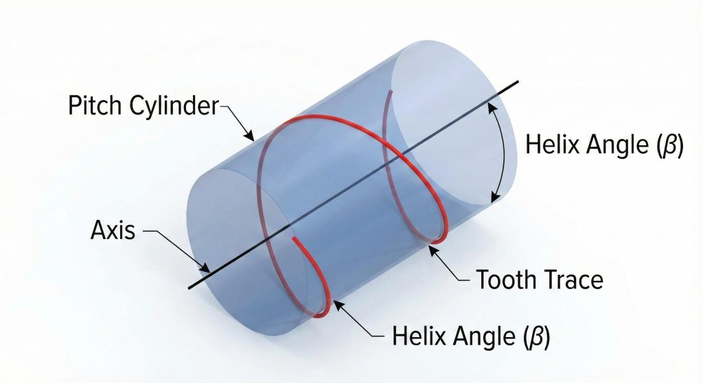
A helix angle helical gear definition refers to the specific inclination of the teeth as they wrap around the cylindrical body of the gear in a screw-like pattern. This angle, typically denoted as beta (β), represents the deviation from the shaft axis and dictates the path the teeth follow along the pitch cylinder. Think about this. Unlike spur gears where teeth are parallel to the shaft, these angled teeth engage progressively, which is fundamental for high-torque applications. You must define this angle accurately in your technical drawings to ensure that CNC machining processes produce a gear that meshes perfectly with its partner.
Pitch Cylinder Relations
The pitch cylinder serves as the reference surface where the helix angle is measured. You will find that the relationship between the cylinder’s circumference and the lead of the helix determines the steepness of the angle.
Geometric Measurements
Measuring the tooth trace involves tracking the spiral path relative to the transverse plane. Accurate geometric verification ensures that the load is distributed evenly across the entire face width of the gear tooth.
| Parameter | Technical Definition | Engineering Significance |
|---|---|---|
| Reference Angle | Degrees from axis (β) | Determines tooth overlap ratio |
| Lead | Axial distance per rotation | Affects gear synchronization |
| Tooth Trace | Path on pitch cylinder | Influences noise reduction levels |
| Normal Pitch | Distance perpendicular to trace | Critical for meshing accuracy |
The technical relationship between the helix angle and the pitch diameter dictates the overall efficiency and load capacity of the gear set.
Key Takeaway: Correct helix angle definition is the foundation for achieving high overlap and smooth engagement in modern transmissions.
How does helix angle helical gear affect performance?
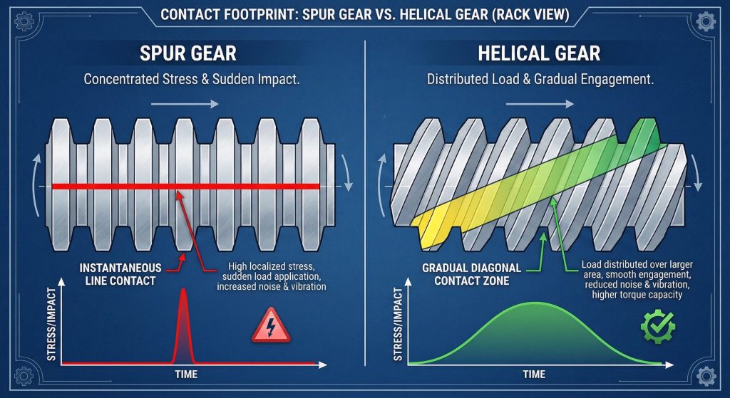
The helix angle helical gear improves performance by increasing the contact ratio and allowing for a smoother, more gradual load transfer between mating teeth. By angling the teeth, you ensure that multiple teeth share the load at any given moment, which prevents the sudden shock loads characteristic of spur gears. Ready for the good part? This increased contact length allows your machinery to transmit higher torque without increasing the physical size of the gearbox. Modern industrial designers prioritize these gears when they need to maximize power density while maintaining operational stability.
Load Distribution Benefits
Gradual engagement means that the total force is spread across a wider surface area. This reduces localized stress at the tooth root, effectively extending the fatigue life of your components.
Torque Transmission Capacity
Because of the increased overlap ratio, these gears can handle significantly higher torque loads than straight-cut alternatives of the same size. You can achieve compact designs without sacrificing the mechanical strength of the drive.
| Metric | Helical Gear Impact | Performance Result |
|---|---|---|
| Overlap Ratio | High (2.0 to 4.5) | Superior torque sharing |
| Impact Force | Gradually Distributed | Reduced mechanical fatigue |
| Load Sharing | Multiple Teeth | Enhanced surface durability |
| Speed Limit | Higher RPM Capacity | Stable high-speed operation |
Optimizing the overlap ratio through precise angle selection leads to higher torque density and smoother power delivery in industrial applications.
Key Takeaway: Performance gains in helical systems are directly tied to the gradual engagement path provided by the helix angle.
Why is helix angle helical gear noise so low?
Low noise levels in a helix angle helical gear result from the teeth engaging in a continuous sliding motion rather than the sudden impact found in standard spur gear sets. As the gears rotate, the contact point travels along the tooth trace, eliminating the loud “whining” sound associated with high-speed transmissions. But wait, there’s more. This silent operation indicates a reduction in mechanical vibration, which also protects the surrounding housing and bearings from resonant damage. You will find that these gears are essential for maintaining a safe and comfortable working environment in large manufacturing plants.
Vibration Dampening Effects
The sliding engagement naturally dampens high-frequency vibrations that would otherwise travel through the gear shaft. This results in a cleaner, more stable rotation that minimizes machine chatter.
Silent Engagement Paths
Precision gear grinding further enhances this quiet performance by removing surface irregularities. When you reduce friction at the microscopic level, the decibel output drops significantly.
| Noise Source | Helical Result | Industrial Advantage |
|---|---|---|
| Tooth Impact | Gradual Sliding | Eliminates gear whine |
| Resonant Vibration | Broadly Dispersed | Lower machine resonance |
| Decibel Rating | 10-15 dB Reduction | Better safety compliance |
| Surface Friction | Optimized Lubrication | Smoother operator experience |
Gradual engagement effectively eliminates the mechanical shock that causes loud operational noise in high-speed industrial transmission systems.
Key Takeaway: Silent operation is a byproduct of the helical design’s ability to engage along a continuous and gradual path.
How to calculate helix angle helical gear dimensions?
You calculate helix angle helical gear dimensions by utilizing the relationship between the normal module and the cosine of the helix angle to find the transverse plane values. This trigonometric conversion is necessary because the tooth size is standardized perpendicular to the helix, but the gear diameter depends on the transverse module. Look. Accurate math prevents backlash and interference issues that could cause your gear set to lock up during heavy service. You must account for the center distance between shafts to ensure the teeth mesh at the correct depth.
Module Conversion Math
The normal module (mn) is your standard tool size, while the transverse module (mt) is calculated by dividing mn by the cosine of the helix angle. This value determines the pitch circle diameter.
Pitch Diameter Formulas
To find the final diameter, you multiply the number of teeth by the transverse module. Every calculation must be verified using internal gear measurement standards to ensure batch consistency.
| Dimension | Formula Symbol | Engineering Utility |
|---|---|---|
| Transverse Module | mt = mn / cosβ | Sets the pitch diameter |
| Center Distance | a = (d1 + d2) / 2 | Fixes shaft positioning |
| Lead | L = π * d / tanβ | Defines CNC tool path |
| Normal Pitch | pn = mt * π * cosβ | Ensures tooth spacing accuracy |
Accurate trigonometric calculations are mandatory for ensuring that helical gears fit perfectly into their designated housing without mechanical interference.
Key Takeaway: Precise module conversion using the helix angle is the only way to determine accurate pitch diameters for helical sets.
What determines helix angle helical gear thrust forces?
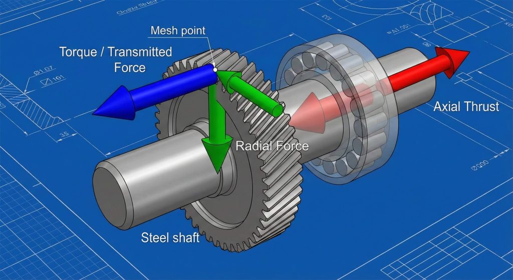
Axial thrust forces in a helix angle helical gear are determined by the magnitude of the helix angle and the total torque being transmitted through the gear teeth. Because the teeth are inclined, a portion of the transmitted force is directed along the shaft axis, attempting to push the gear laterally. Ready for the good part? You can manage these forces effectively by selecting tapered roller bearings or by utilizing a double helical design that cancels out the internal pressures. If you neglect these thrust calculations, your gearbox will likely suffer from shaft misalignment and bearing failure.
Axial Load Factors
Higher helix angles provide quieter operation but generate significantly more axial thrust. You must find a balance that your gear shaft and bearing arrangement can realistically support.
Bearing Requirements
Using angular contact or tapered bearings is standard practice for handling these lateral loads. These components ensure that the gear remains in its intended axial position during the highest torque cycles.
| Load Type | Direction | Mitigation Strategy |
|---|---|---|
| Axial Thrust | Parallel to Shaft | Tapered Roller Bearings |
| Tangential Force | Circumferential | High-Alloy Material Selection |
| Radial Force | Perpendicular to Axis | Deep Groove Ball Bearings |
| Resultant Force | Combined Vector | Reinforced Housing Design |
Properly managing axial thrust is critical for preventing shaft displacement and ensuring the long-term reliability of the entire drive assembly.
Key Takeaway: Axial thrust is a direct function of the helix angle and requires robust bearing support for operational stability.
Can a helix angle helical gear improve efficiency?
A helix angle helical gear improves efficiency by reducing mechanical vibration and distributing friction more evenly across the tooth flank during high-speed rotation. While the sliding action does generate slightly more heat than a spur gear, the increased overlap ratio ensures a more consistent transfer of energy. Think about this. High-quality surface finishes and the right synthetic lubricants can offset any sliding losses, making these gears highly efficient for modern power transmissions. You will notice lower energy consumption when your gear sets operate without the jerky motion of straight-cut alternatives.
Energy Transfer Consistency
The continuous contact path ensures that torque remains stable throughout the rotation. This stability reduces the parasitic energy losses often seen in vibrating or poorly aligned gear systems.
Lubrication Impact
A consistent oil film is easier to maintain on helical teeth due to the sliding engagement. Using high-performance lubricants ensures that your bevel gear and helical sets run with minimal thermal waste.
| Factor | Helical Benefit | Efficiency Result |
|---|---|---|
| Vibration | Minimal Resonance | Lower energy dissipation |
| Surface Contact | Broad Distribution | Optimized friction profile |
| Torque Flow | Constant/Stable | Reduced power spikes |
| Heat Generation | Managed Sliding | Sustainable high-speed work |
High-quality manufacturing and precision grinding maximize the energy efficiency of helical gear sets by reducing internal friction and heat generation.
Key Takeaway: Efficiency improves when helix angles are optimized alongside precision surface finishes and proper lubrication strategies.
Which hand suits a helix angle helical gear pair?
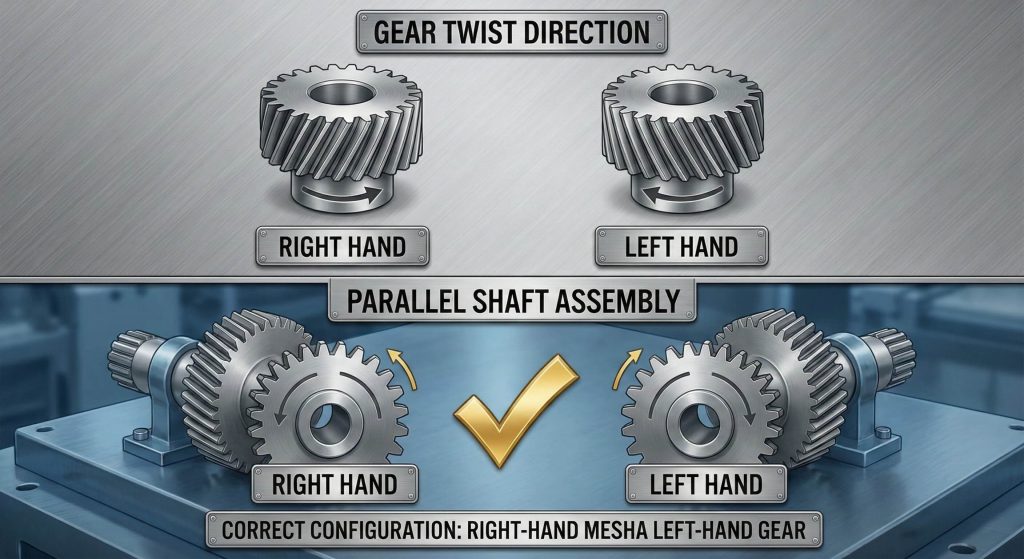
Selecting the correct hand for a helix angle helical gear pair depends on whether the shafts are parallel or crossed, requiring opposite or matching directions respectively. For standard parallel shaft arrangements, you must use one right-handed gear and one left-handed gear to allow the teeth to nest together. Here is the deal. If you attempt to mesh two gears of the same hand on parallel shafts, the teeth will clash and cause mechanical failure. You can easily identify the hand by holding the gear vertically and observing the upward twist of the teeth.
Right-Hand vs Left-Hand
A right-hand helix twists upward to the right, while a left-hand helix twists to the left. Visual verification is your first line of defense against costly assembly errors on the shop floor.
Parallel Shaft Mesh
In a parallel drive, the opposite angles of the two gears ensure that the contact line remains straight across the face width. This setup is the most common configuration in industrial machinery.
| Configuration | Gear 1 Hand | Gear 2 Hand | Meshing Result |
|---|---|---|---|
| Parallel Shafts | Right-Hand | Left-Hand | Standard Alignment |
| Crossed Shafts | Right-Hand | Right-Hand | 90-Degree Transmission |
| Assembly Error | Left-Hand | Left-Hand | Immediate Interference |
| Custom Drive | Right-Hand | Left-Hand | Non-Standard Angle |
Correct hand matching is the most basic yet vital step in ensuring that helical gears mesh correctly within a parallel shaft arrangement.
Key Takeaway: Always use opposite-handed gears for parallel shafts and same-handed gears for crossed-axis applications to ensure proper meshing.
How does helix angle helical gear impact durability?
Durability increases in a helix angle helical gear because the angled tooth design provides a larger root section and minimizes localized stress concentrations during operation. The gradual engagement eliminates the hammering effect that often chips the teeth of spur gears, resulting in a significantly longer service life. Bottom line. You can transmit higher loads for more hours with less risk of catastrophic fatigue failure. Investing in these components reduces your long-term downtime and keeps your production lines running with predictable maintenance schedules.
Fatigue Resistance
The inclined tooth profile is naturally stronger than a straight tooth because its base is thicker in the plane of rotation. This geometry resists the bending stresses that lead to root cracks.
Wear Longevity
Uniform load distribution across the face width prevents localized pitting and surface wear. You will find that the teeth maintain their precision profile for years, even under aggressive industrial duty cycles.
| Feature | Helical Advantage | Durability Outcome |
|---|---|---|
| Root Strength | Higher Base Area | 30% Better Fatigue Life |
| Impact Stress | Distributed Load | Reduced Pitting Risk |
| Surface Wear | Uniform Pattern | Prevents Edge Chipping |
| Material Stress | Lower Localized Peak | Absorbs Sudden Shocks |
The inherent geometric strength of helical teeth combined with gradual engagement significantly extends the operational lifespan of industrial gearboxes.
Key Takeaway: Enhanced durability stems from the helical tooth’s ability to resist fatigue and distribute loads across a larger surface area.
What is the best helix angle helical gear material?
The best material for a helix angle helical gear is typically a high-grade alloy steel like 20CrMnTi that has undergone precision carburizing for surface hardness. You need a material that offers a hard, wear-resistant exterior shell while maintaining a tough, ductile core to absorb shock loads. Here is the kicker. Using low-quality steel will lead to rapid surface degradation due to the sliding friction inherent in helical designs. You should always request material traceability reports to ensure your gears can handle the thermal and mechanical stresses of your application.
Alloy Selection
Alloys such as 18CrNiMo7-6 are preferred for heavy-duty wind turbine or mining applications because they offer exceptional toughness. These metals maintain their dimensional stability even after intensive heat treatment.
Heat Treatment
Carburizing followed by quenching provides the HRC 58-62 surface hardness needed for long-term stability. This process ensures that the sliding teeth do not gall or overheat during high-speed rotation.
| Grade | Key Property | Common Application |
|---|---|---|
| 20CrMnTi | Carburizing Steel | Automotive Transmissions |
| 42CrMo | High Strength | Heavy Industrial Drives |
| 18CrNiMo7-6 | Extreme Toughness | Renewable Energy Units |
| SCM415 | Wear Resistance | Precision Machine Tools |
Selecting the right alloy steel and heat treatment process is the only way to ensure that helical gears survive in high-torque industrial applications.
Key Takeaway: Carburized alloy steels provide the best combination of surface hardness and core strength for high-performance helical gears.
How to inspect helix angle helical gear precision?
You inspect helix angle helical gear precision using coordinate measuring machines (CMM) that verify the involute profile and lead accuracy against your original CAD models. Specialized gear measurement centers track the spiral tooth trace to ensure the helix angle remains consistent throughout the entire face width. Think about this. Even a minor deviation in the lead can cause uneven contact patterns, leading to vibration and premature failure. You must demand full inspection documentation, including lead error and pitch variation reports, to guarantee the quality of your parts.
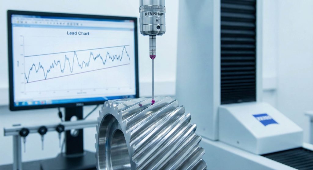
CMM Verification
Probes measure thousands of points along the tooth flank to create a digital map of the gear geometry. This data is compared to the theoretical tooth form to identify any manufacturing errors.
Quality Control
In-process checks during hobbing and grinding ensure that any thermal distortion from heat treatment is corrected. High-precision gears typically meet ISO Grade 6 standards for demanding industrial environments.
| Metric | Tolerance Target | Measurement Tool |
|---|---|---|
| Helix Deviation | < 10 Microns | Gear Measurement Center |
| Involute Profile | ISO Grade 6 | Coordinate Measuring Machine |
| Surface Finish | Ra 0.8 or Better | Surface Profilometer |
| Lead Accuracy | Constant Slope | Specialized Tracer Probe |
Advanced measurement technology is essential for verifying the complex spiral geometry of helical gears and ensuring they meet strict industrial standards.
Key Takeaway: Comprehensive inspection using specialized gear measurement centers is the only reliable way to guarantee helical gear accuracy.
Conclusion
Selecting a precision helix angle helical gear is the most effective way to optimize your mechanical drive systems for quiet, efficient, and durable performance. This technical guide has detailed how tooth inclination influences noise levels, load-carrying capacity, and overall energy efficiency in industrial settings. By understanding the geometric requirements and material strategies, you can design gearboxes that outperform standard spur gear configurations in every metric. We provide the engineering-backed manufacturing needed to produce these high-performance components with full traceability and documented accuracy. We encourage you to reach out to our technical team today to discuss your specific transmission requirements and receive a detailed proposal.
FAQ
Q1: Can I use different helix angles for parallel shafts?
No. Mating gears on parallel shafts must have perfectly identical helix angles to ensure the teeth mesh correctly across the entire face width without causing point-contact stress.
Q2: What’s the best way to handle axial thrust?
The best way is to utilize tapered roller bearings or angular contact bearings, which are specifically designed to absorb the lateral forces generated by the helical tooth trace.
Q3: How do I know if a helical gear is better than a spur gear?
You should choose a helical gear if your application requires high-speed rotation, low noise levels, or higher torque capacity within a compact housing design.
Q4: Can a higher helix angle reduce noise further?
Yes. Increasing the angle generally improves the overlap ratio and reduces noise, but you must account for the resulting increase in axial thrust forces that your bearings must support.
Q5: What’s the deal with gear hand compatibility?
For parallel shafts, you must use one right-hand and one left-hand gear, whereas crossed-axis drives require both gears to have the same hand to function properly.