The helical gear ratio is the mathematical relationship between the number of teeth on the driving gear and the driven gear, determining the output speed and torque. This specific ratio defines how many times the input shaft must rotate to complete a single full rotation of the output shaft. By utilizing angled teeth, these gears provide a smoother and quieter power transmission than traditional straight-cut designs. You will find that this fixed mechanical link is essential for synchronizing industrial machinery across various automation sectors.
What exactly is a helical gear ratio?
A helical gear ratio is the numerical value that describes the proportional change in rotational velocity between two interlocking gears. This value is a physical constant that determines the mechanical advantage gained within a transmission system. In a standard setup, the helical gear ratio ensures that power is transferred with zero slippage and consistent timing. You can rely on this metric to predict the final performance of any gear-driven industrial application.
Think about it:
The Nature of Mechanical Advantage
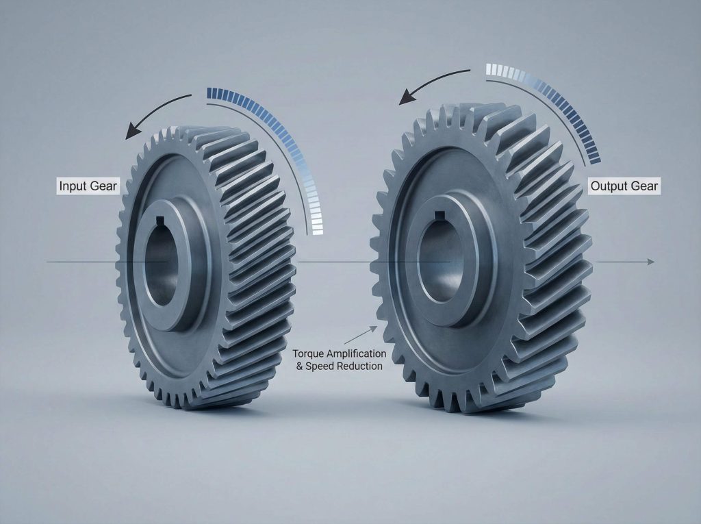
The ratio acts as a bridge between high-speed motor outputs and the high-torque requirements of heavy machinery. It allows small motors to move immense loads by sacrificing rotational speed for increased turning force.
- Input gears typically rotate faster than output gears.
- Speed reduction is inversely proportional to the ratio.
- Torque multiplication is directly proportional to the ratio.
Key Takeaway: The gear ratio is the fundamental blueprint for controlling speed and force within a helical power transmission assembly.
| Component Type | Rotational Role | Impact on Ratio |
|---|---|---|
| Driver Gear | Input Power | Sets the base speed |
| Driven Gear | Output Power | Defines final velocity |
| Idler Gear | Directional | Does not change ratio |
Precision in ratio selection is the primary driver of operational efficiency in high-load environments.
How do you calculate the helical gear ratio?
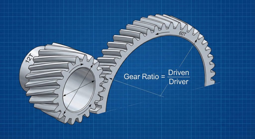
You calculate the helical gear ratio by dividing the number of teeth on the driven gear by the number of teeth on the driving gear. This formula remains consistent across all mechanical gear sets regardless of the tooth angle or gear diameter. For example, a 60-tooth gear driven by a 12-tooth gear results in a 5:1 reduction. You must always use the physical tooth count to ensure an accurate mathematical result for your engineering projects.
Here is the kicker:
Applying the Standard Formula
The simplicity of this calculation allows engineers to quickly determine the output speed of any gearbox during the design phase. It provides a reliable way to match motor performance with specific production line requirements.
- Count the teeth on the output component.
- Count the teeth on the input component.
- Divide the larger number by the smaller number.
Key Takeaway: Dividing the driven teeth by the driving teeth provides the exact mechanical advantage of any helical gear set.
| Driving Teeth | Driven Teeth | Calculated Ratio | Speed Reduction |
|---|---|---|---|
| 10 | 40 | 4:1 | 75% |
| 15 | 45 | 3:1 | 66.7% |
| 20 | 100 | 5:1 | 80% |
Understanding these basic divisions helps prevent motor overloads and ensures long-term hardware reliability.
Does the helix angle change the gear ratio?
The helix angle does not change the helical gear ratio because the ratio is dictated strictly by the physical count of interlocking teeth. While a steeper angle increases the contact surface and reduces operational noise, it has no effect on the circular distance traveled per rotation. You can adjust the angle to optimize for load capacity or vibration without altering the speed of your output shaft. This independence allows for flexible design when integrating a bevel gear or helical set into existing systems.
Wait, there’s more:
Tooth Geometry and Performance
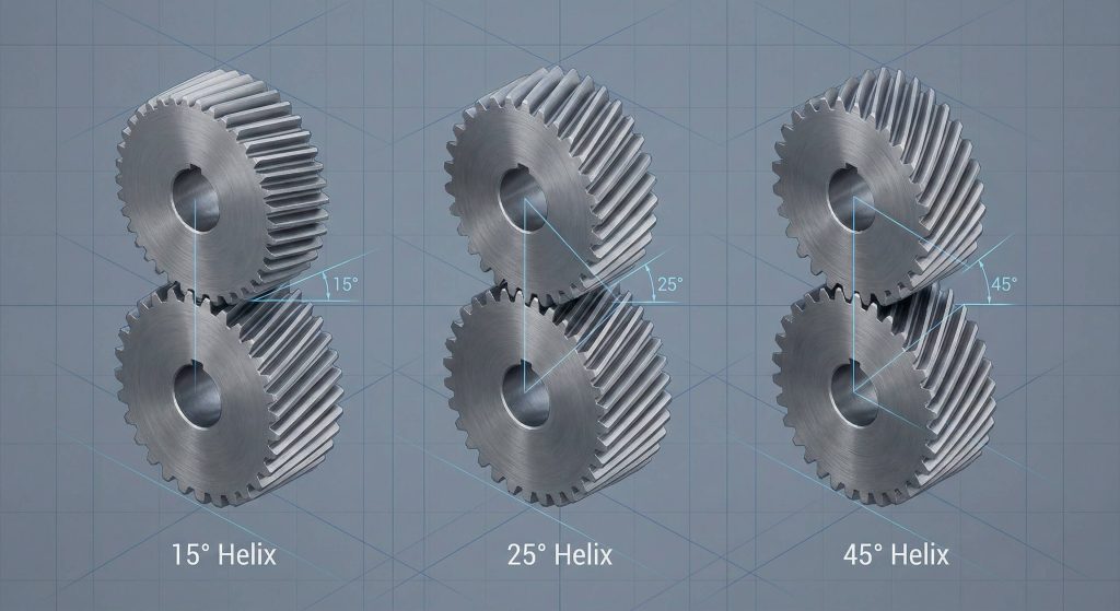
The angle primarily influences the smoothness of the transition between teeth as they enter and exit the mesh zone. It manages the axial thrust and noise levels but leaves the speed-to-torque conversion ratio untouched.
- Angles usually vary between 15 and 30 degrees.
- Steeper angles provide superior noise dampening.
- Thrust bearings must manage the resulting axial force.
Key Takeaway: Helix angles improve the quality of power delivery but do not interfere with the mathematical gear ratio calculation.
| Angle Setting | Noise Level | Axial Thrust | Ratio Impact |
|---|---|---|---|
| 15 Degrees | Moderate | Low | None |
| 25 Degrees | Low | Moderate | None |
| 45 Degrees | Minimal | High | None |
Engineers prioritize helix angles for durability and acoustic performance rather than speed adjustment.
Why does tooth count determine the ratio?
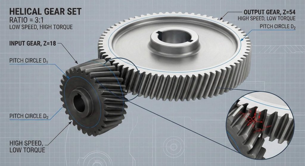
Tooth count determines the helical gear ratio because it establishes a fixed physical lock that synchronizes the movement of both the input and output shafts. Since each tooth on the driver must engage a corresponding slot on the driven gear, the speed relationship is effectively hard-wired into the hardware. If the driven gear has twice as many teeth, it will move at half the speed of the driver. You can rely on this mechanical synchronization to maintain the perfect timing required for high-precision manufacturing.
The best part?
The Mechanics of Interlocking Teeth
This physical engagement prevents any relative slipping that could disrupt the timing of automated production cycles. It ensures that every rotation of the motor results in a predictable and repeatable movement of the final tool.
- Teeth act as a physical timing mechanism.
- Pitch diameter grows as tooth count increases.
- Mechanical leverage is a direct result of size gaps.
Key Takeaway: Tooth counts serve as the physical foundation for the synchronization and torque multiplication in any gear-driven system.
| Gear Position | Teeth Volume | Shaft Speed | Torque Output |
|---|---|---|---|
| Input | Low | High | Low |
| Output | High | Low | High |
| Idler | Fixed | Constant | None |
Consistent tooth counts guarantee that the gear ratio remains stable regardless of environmental temperature or wear.
What are standard helical gear ratio ranges?
Standard helical gear ratios typically range from 1.5:1 to 10:1 for single-stage reductions in most industrial gearboxes. These ranges are optimized to provide significant torque multiplication while keeping the physical size of the gear shaft and housing within manageable limits. Manufacturers focus on these standard increments to ensure that components are readily available and cost-effective for end-users. You will find that most factory conveyor systems and pumps utilize ratios within this common spectrum for peak efficiency.
Look at it this way:
Industry Standard Applications
Ratios are selected based on the specific speed requirements of the application and the power limitations of the drive motor. Selecting a standard ratio helps simplify future maintenance by allowing for the use of off-the-shelf replacement parts.
- 3:1 is common for high-speed automated sorting.
- 5:1 is a standard choice for heavy conveyor belts.
- 10:1 represents the upper limit for single-stage housings.
Key Takeaway: Standard ratios balance the need for mechanical advantage with the practical constraints of gearbox size and cost.
| Application | Common Ratio | Primary Goal |
|---|---|---|
| Pumping | 2:1 to 5:1 | Continuous Flow |
| Conveyors | 5:1 to 15:1 | Managed Velocity |
| Crushing | 20:1+ | Extreme Force |
Staying within standard ranges reduces manufacturing lead times and improves the long-term serviceability of the equipment.
Can multi-stage sets boost the gear ratio?
Multi-stage assemblies can significantly boost the helical gear ratio by compounding the reduction effects of several gear pairs within a single unit. When a single stage cannot achieve the required speed reduction, engineers add additional shafts to multiply the mechanical advantage exponentially. For instance, combining two 10:1 stages results in a massive 100:1 total reduction for the system. You should use multi-staging for any application that requires extreme torque or very slow rotational speeds.
The kicker is this:
Compound Reduction Dynamics
As each stage reduces the speed, it simultaneously multiplies the torque delivered to the next set of gears in the sequence. This cumulative process allows a small electrical motor to generate enough force to move hundreds of tons of material.
- Final ratio is the product of all internal stages.
- Multi-staging allows for compact high-torque designs.
- Total efficiency drops slightly with each added stage.
Key Takeaway: Multi-stage helical configurations compound individual gear ratios to provide the massive torque required for the heaviest industrial tasks.
| Stage Count | Math Calculation | Final Ratio | Output Torque |
|---|---|---|---|
| 1 Stage | 5 / 1 | 5:1 | 500% |
| 2 Stages | 5 * 5 | 25:1 | 2500% |
| 3 Stages | 5 * 5 * 4 | 100:1 | 10,000% |
Multi-stage gearboxes offer the highest power density available in modern mechanical transmission systems.
How does gear ratio affect output torque?
Output torque increases in direct proportion to the helical gear ratio as the speed of the output shaft decreases. This is a primary law of physics: as you use gears to slow down a motor, the energy is transformed into a more powerful twisting force. For example, a 10:1 ratio will theoretically deliver ten times the motor’s torque to the load. You can utilize a planetary gear or helical set to achieve these massive force gains in a very small footprint.
Think about it:
The Relationship of Power and Force
This transformation of energy is what allows heavy machinery to start moving under the stress of a full load. Without a high gear ratio, most industrial motors would simply stall when attempting to overcome the initial inertia of the equipment.
- Torque gain is the inverse of speed reduction.
- High ratios are critical for heavy-duty lifting.
- Shaft materials must be rated for the final output force.
Key Takeaway: Gear ratios act as a force multiplier, allowing you to convert high-speed rotation into the raw power needed for industrial work.
| Ratio Level | Speed Loss | Torque Multiplication | Best Use Case |
|---|---|---|---|
| Low (2:1) | 50% | 2x | High Velocity Fans |
| Mid (10:1) | 90% | 10x | Standard Conveyors |
| High (50:1) | 98% | 50x | Heavy Winches |
Managing this torque increase is essential for preventing internal component failure under extreme mechanical stress.
Is system efficiency linked to the ratio?
System efficiency is linked to the helical gear ratio because higher ratios often require more internal components that generate frictional heat. While a single-stage helical set typically operates at 98% efficiency, adding stages to achieve a 100:1 ratio can drop that figure significantly. Each point where gear teeth mesh creates a small amount of sliding friction that consumes a portion of the input energy. You must prioritize high-quality synthetic lubricants to maintain peak performance in high-ratio assemblies.
Here is the kicker:
Minimizing Energy Loss
Helical gears are generally more efficient than other types like worm gears because their contact involves more rolling and less sliding. This superior geometry allows them to stay cooler and last longer during continuous high-speed operation.
- Single stages are the most energy efficient.
- Precision grinding reduces friction at the mesh.
- Bearings must be optimized for axial thrust loads.
Key Takeaway: While high ratios can lead to minor efficiency losses through multi-staging, helical gears remain one of the most efficient transmission options available.
| Gear Setup | Stage Efficiency | Total Loss | Thermal Output |
|---|---|---|---|
| Single Helical | 98% | 2% | Very Low |
| Triple Helical | 94% | 6% | Moderate |
| Standard Worm | 70% | 30% | Very High |
Selecting a helical configuration ensures your facility minimizes electrical waste while maximizing mechanical output.
What limits a single stage gear ratio?
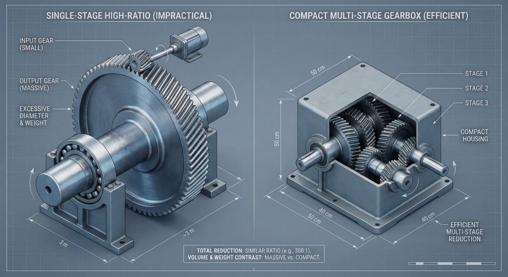
Physical size and manufacturing costs are the primary factors that limit the maximum ratio achievable in a single stage. If you attempted to create a 30:1 ratio with just two gears, the driven gear would be thirty times larger than the input pinion. This would result in a massive housing that is difficult to fit into standard machines and very expensive to produce. Most engineers switch to a spur gear or helical multi-stage design once the required reduction exceeds 10:1 to maintain practicality.
Look at it this way:
Practical Design Constraints
Oversized gears are also prone to dynamic balancing issues and thermal warping during the heat treatment process. Keeping gear diameters smaller allows for higher precision and lower centrifugal forces during high-speed rotation.
- Large housings require specialized foundations.
- Manufacturing costs grow exponentially with size.
- Multi-stage units offer better power density.
Key Takeaway: Space constraints and manufacturing complexity limit single-stage helical ratios to approximately 10:1 for most industrial applications.
| Constraint | Impact on Design | Best Solution |
|---|---|---|
| Housing Volume | High Size | Multi-staging |
| Weight | Increased Stress | Alloy materials |
| Precision | Difficulty | Grinding teeth |
Compact designs are always preferred for modern automation because they save space and reduce the total cost of ownership.
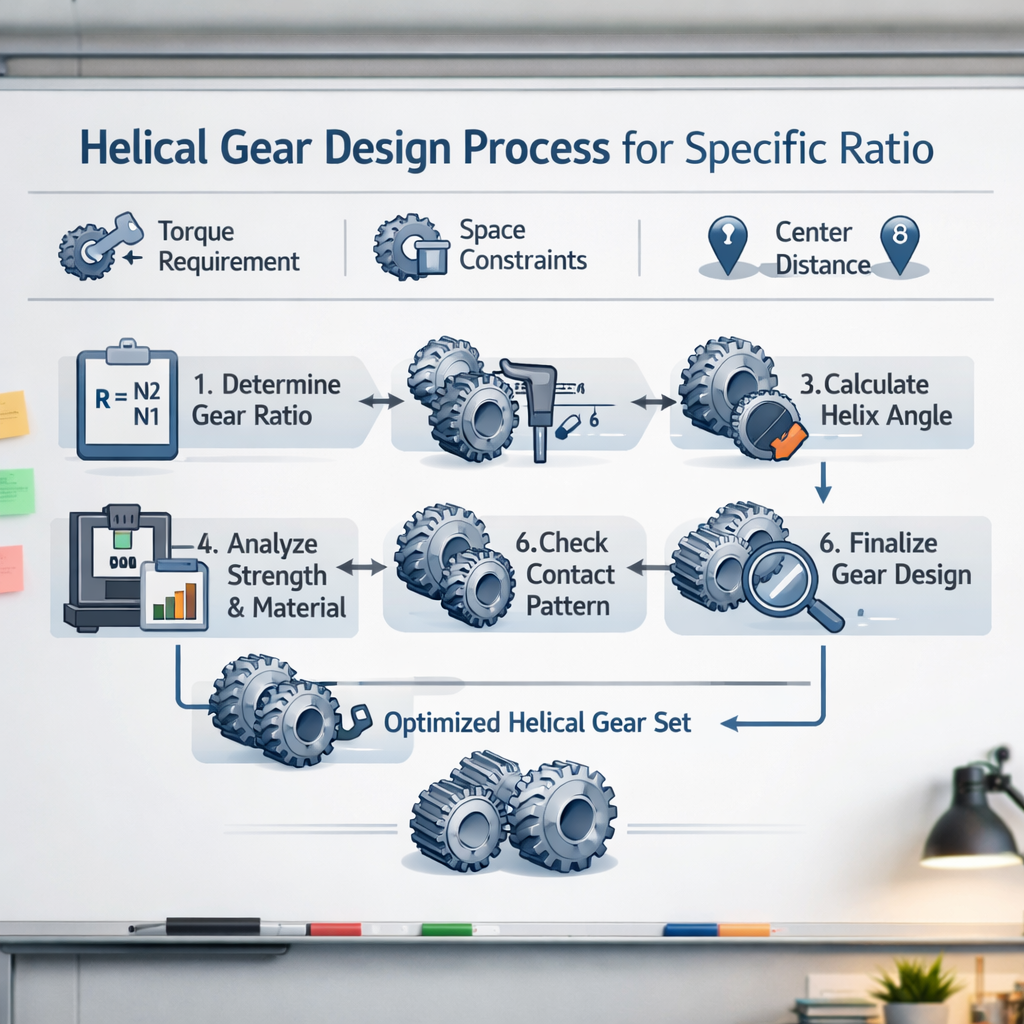
How do you choose the right gear ratio?

You choose the right gear ratio by analyzing the output speed of your motor and the specific torque requirements of your internal gear assembly. First, calculate the target RPM needed for your machine to operate at its peak production rate. Then, divide the motor’s full-load speed by that target value to find the baseline helical gear ratio for your gearbox. It is vital to include a safety factor of 1.2 to 1.5 to ensure the system can handle unexpected shock loads or startups.
Wait, there’s more:
Precision Selection Process
Choosing a ratio is not just about speed; it is about protecting your motor from overheating by providing sufficient mechanical advantage. An undersized ratio will cause the motor to draw too much current, leading to premature electrical failure and downtime.
- Identify the required final shaft RPM.
- Determine the breakaway torque needed.
- Factor in the operational duty cycle.
Key Takeaway: The ideal gear ratio balances the need for speed with the requirement for force while ensuring long-term motor and gearbox health.
| Selection Step | Critical Action | Desired Result |
|---|---|---|
| 1. RPM Check | Measure final speed | Defines ratio |
| 2. Torque Load | Calculate resistance | Protects gears |
| 3. Safety Margin | Add 20-50% buffer | Ensures longevity |
| 4. Housing Fit | Verify dimensions | Easy installation |
Proper ratio selection is the cornerstone of a reliable and efficient industrial power transmission strategy.
FAQ
Can I change the gear ratio by only replacing one helical gear in a set?
No. You must always replace helical gears as a matched pair because the helix angles, pressure angles, and tooth profiles must be perfectly aligned to mesh correctly. Changing only one gear will cause immediate misalignment and lead to catastrophic failure.
What’s the best way to determine if my ratio is causing motor overheating?
Check the current draw. If your motor is consistently pulling more than its rated amperage while running at full speed, your gear ratio is likely too low, forcing the motor to work harder than intended to move the load.
How do I know when to switch from a single-stage to a multi-stage helical gearbox?
Switch when your ratio exceeds 10:1. At this point, a single-stage unit becomes too large and inefficient, whereas a multi-stage unit will offer a more compact and cost-effective solution for your transmission needs.
Can I use a higher ratio to save money on a smaller motor?
Yes, but with caution. While a higher ratio increases torque, it also reduces speed significantly; you must ensure the final output speed still meets your production requirements before downsizing your motor.
How do I know if my gear ratio is precisely accurate for my timing-sensitive application?
Count the teeth on both gears. Because gears are mechanical links with no slippage, the ratio is a fixed mathematical absolute; as long as the tooth count is correct, the ratio will never change during operation.
Conclusion
The mathematical precision of the helical gear ratio is the defining factor in modern industrial efficiency, allowing for the perfect transformation of motor power into mechanical work. By understanding how to calculate these values and the physical limits of gear design, you can ensure your machinery operates with maximum reliability and minimal noise. Our team is dedicated to providing the high-performance components you need to keep your facility running at peak capacity. If you are ready to upgrade your drivetrain or need expert advice on ratio selection, please contact us today to speak with our engineering specialists.