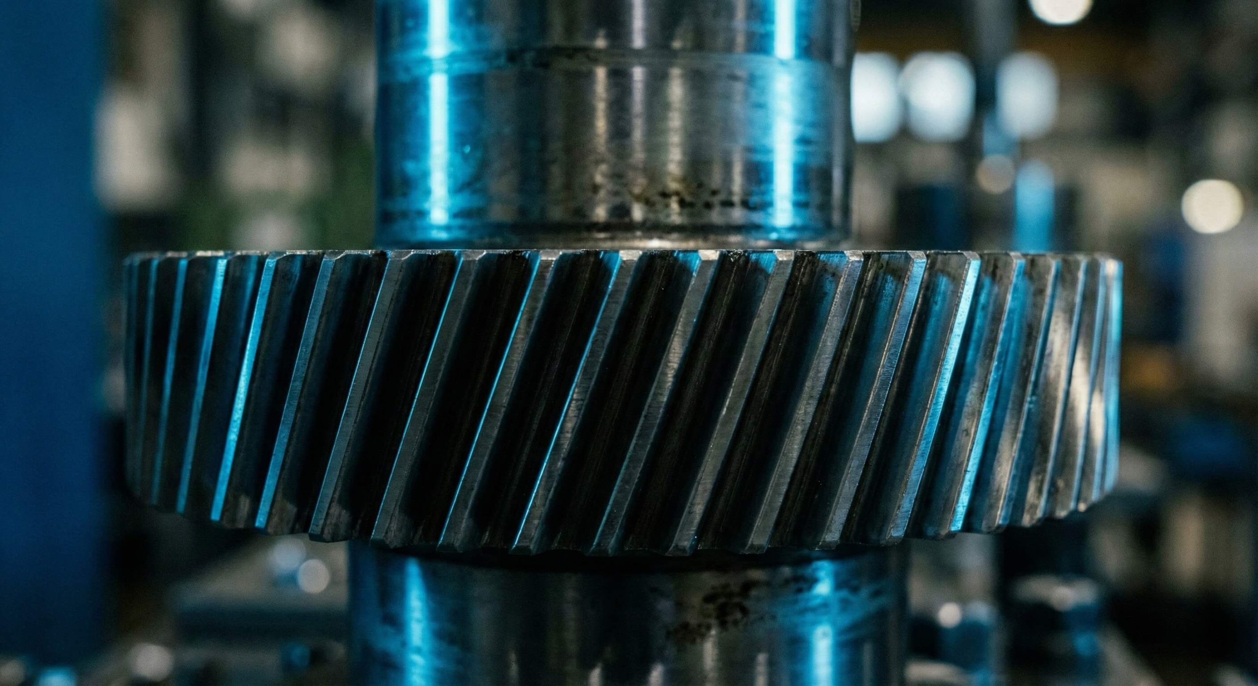
Constant gear chatter and mechanical vibration often indicate that your drive system is nearing a structural failure. These fluctuations agitate your production schedule by forcing unexpected repairs and increasing your long-term energy overhead. You can solve these stability issues by installing a high-precision helical gear wheel into your transmission assembly. A helical gear wheel is a cylindrical power transmission component featuring teeth cut at an angle to the axis of rotation.
What is the benefit of a helical gear wheel?
The primary benefit of a helical gear wheel is its ability to transmit power quietly while handling significantly higher loads than straight-cut gears. You will find that the angled teeth engage gradually, which distributes force more effectively across the gear face. This results in a transmission system that remains stable under extreme mechanical stress.
Achieving Superior Noise Reduction
You can drastically lower the decibel levels in your facility by switching to helical designs. The gradual engagement of the teeth prevents the sudden impact noise typical of spur gears.
Think about it:
- Quiet operation improves the workplace environment.
- Reduced vibration protects sensitive electronic components.
- Smooth transitions extend the life of your bearings.
Increasing Maximum Load Capacity
The increased contact ratio of a helical gear wheel allows it to carry more torque within a smaller footprint. This geometric advantage is vital for space-constrained industrial gearboxes.
Here is the deal:
- Higher power density optimizes your machine design.
- Distributed stress prevents individual tooth fractures.
- Enhanced durability reduces the frequency of replacements.
Key Takeaway: Helical geometry provides the dual advantage of high torque capacity and near-silent operation in heavy-duty applications.
| Feature | Industrial Benefit |
|---|---|
| Angled Tooth Trace | Gradual Meshing |
| High Contact Ratio | Load Distribution |
| Helical Overlap | Vibration Dampening |
This data confirms that helical designs outclass spur gears in both acoustic and structural performance metrics.
How does a helical gear wheel mesh smoothly?

A helical gear wheel meshes smoothly through a continuous sliding action that eliminates the “hammering” effect found in standard designs. You will observe that the contact begins at one end of the tooth and progresses seamlessly across its entire width. This ensures that power delivery remains constant throughout the entire rotational cycle.
Understanding the Sliding Contact
The sliding nature of the mesh allows for a more fluid transfer of rotational energy. You must ensure proper lubrication to manage the friction inherent in this high-performance movement.
Check this out:
- Continuous contact maintains steady output velocity.
- Sliding action helps spread the lubricant film.
- Improved mesh efficiency reduces heat buildup.
The Role of Helical Overlap
Helical overlap occurs when multiple teeth share the load simultaneously during the rotation. This redundancy ensures that your machinery never experiences a total loss of contact between the driving and driven components.
Wait, there is more:
- Redundant contact points prevent sudden torque dips.
- Overlap improves the overall safety factor of the drive.
- Shared stress leads to more predictable wear patterns.
Key Takeaway: The sliding meshing action ensures a constant velocity and prevents the mechanical shocks associated with tooth transitions.
| Meshing Property | Performance Result |
|---|---|
| Sliding Path | Smooth Engagement |
| Multiple Tooth Contact | Uniform Load |
| Overlap Ratio | Torque Stability |
Sliding mechanics are the foundation of the high-speed stability required by modern automated production lines.
Which materials suit a helical gear wheel?
The best material for a helical gear wheel is typically high-grade alloy steel that has undergone precision heat treatment. You must select alloys that offer a hard, wear-resistant surface combined with a tough, impact-resistant core. Using the right material prevents the surface pitting that often ruins lower-quality gear sets.
Selecting Industrial Grade Steels
Most heavy-duty gears utilize materials like SCM440 or SNCM439 for their superior fatigue strength. These steels respond well to carburizing and quenching processes.
Consider this:
- Alloy steels resist deformation under high torque.
- Case hardening creates a durable exterior shell.
- Full traceability ensures consistent material quality.
Exploring Alternative Gear Polymers
You can use high-performance polymers for light-duty or self-lubricating applications where noise is a critical concern. These materials are perfect for medical devices or high-precision office equipment.
Here is the kicker:
- Nylon and POM offer excellent chemical resistance.
- Plastic gears require no external oil or grease.
- Weight reduction improves the efficiency of portable tools.
Key Takeaway: Material selection is the primary factor determining the longevity and load limits of your transmission system.
| Material | Best Application | Key Property |
|---|---|---|
| Forged Alloy Steel | Heavy Mining & Energy | High Impact Resistance |
| Carbon Steel | Industrial Conveyors | Versatility & Value |
| Engineering Plastic | Food & Medical Tech | Cleanliness & Low Weight |
Matching material properties to operational loads is essential for preventing premature mechanical fatigue.
Why does a helical gear wheel produce thrust?
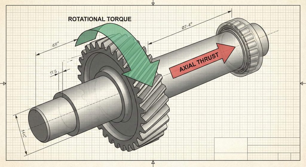
A helical gear wheel produces thrust because its angled teeth generate a force vector that is parallel to the shaft. You will need to account for this axial load to prevent the gear from shifting out of its housing. This unique characteristic requires specific bearing configurations to ensure the gearbox remains structurally sound.
Managing the Axial Force Vector
The axial force is a natural byproduct of the helix angle designed into the gear teeth. You can calculate this force based on the torque load and the specific angle of the gear.
Look closer:
- Higher helix angles produce more axial thrust.
- Thrust direction depends on the gear’s rotation.
- Proper housing design prevents axial displacement.
Utilizing Specialized Thrust Bearings
You must use tapered roller bearings or angular contact bearings to effectively manage these axial loads. These components allow the shaft to rotate freely while resisting the lateral pressure generated by the mesh.
Think about this:
- Tapered rollers handle both radial and axial loads.
- Proper bearing preload ensures long-term stability.
- Thrust management prevents casing wear and failure.
Key Takeaway: Axial thrust is a manageable side effect of the helical design that requires dedicated bearing support.
| Support Strategy | Component Used | Effectiveness |
|---|---|---|
| External Support | Tapered Roller Bearing | Very High |
| Internal Balancing | Double Helical Design | Superior |
| Basic Management | Ball Thrust Bearing | Moderate |
Properly addressing thrust forces is mandatory to prevent the internal destruction of the gearbox assembly.
How do you lubricate a helical gear wheel?
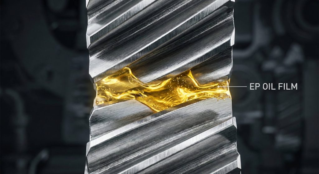
You lubricate a helical gear wheel by applying specialized extreme-pressure (EP) oils that maintain a protective film on the sliding surfaces. Because the teeth slide against each other, they require more robust lubrication than standard spur gears. Regular oil analysis is your best defense against the abrasive wear caused by metal-on-metal contact.
Choosing the Correct Oil Viscosity
Selecting the right viscosity ensures that the oil film is thick enough to separate the gear teeth under load. You should consult your equipment manual to find the ISO grade that matches your operating temperature.
Check this out:
- EP additives prevent surface scuffing and scoring.
- Synthetic oils offer better performance at high heat.
- Correct viscosity reduces internal friction and heat.
Maintaining Seal and Fluid Integrity
You must keep your gearbox seals in perfect condition to prevent oil leaks and external contamination. Dirt or water entering the system will act as an abrasive, rapidly destroying your high-precision gears.
Wait, there is more:
- Clean breathers prevent internal pressure spikes.
- Magnetic drain plugs capture harmful metal particles.
- Regular oil changes flush out microscopic wear debris.
Key Takeaway: Consistent lubrication with high-quality EP oil is the single most effective way to extend gear life.
| Lubrication Type | Best Environment | Maintenance Cycle |
|---|---|---|
| Splash Lubrication | Fully Enclosed Box | 1,000 Hours |
| Forced Feed | High-Speed Systems | 500 Hours |
| Manual Grease | Open Gear Drives | Weekly |
Fluid film maintenance represents the most critical recurring task for industrial maintenance teams.
How is a helical gear wheel manufactured?
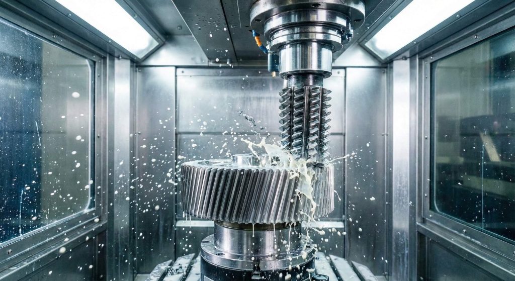
Manufacturing a helical gear wheel involves specialized CNC gear hobbing machines that can follow the required helix angle. You start with a forged blank that is precisely machined to ensure concentricity and balance. Advanced manufacturing ensures that the tooth profile meets international accuracy standards like ISO 1328 Grade 6.
The CNC Hobbing Process
CNC hobbing is the industry standard for creating accurate helical tooth profiles on mass-produced parts. You will benefit from the high repeatability and tight tolerances that modern automated machinery provides.
Look closer:
- Precise indexing ensures uniform tooth thickness.
- Automated cooling prevents thermal distortion during cutting.
- Multi-axis control allows for complex gear geometries.
Final Grinding and Heat Treatment
You should prioritize ground gears for high-speed applications where noise and friction must be minimized. The grinding process removes minor deviations caused by the heat treatment phase, resulting in a mirror-like finish.
Ready for the good part?
- Profile grinding achieves sub-micron precision levels.
- Induction hardening provides specific surface durability.
- Ground teeth offer the most efficient power transfer.
Key Takeaway: Precision manufacturing through CNC hobbing and grinding is essential for high-performance industrial gears.
| Production Step | Technology Used | Output Quality |
|---|---|---|
| Gear Hobbing | Multi-axis CNC | Standard Precision |
| Profile Grinding | Abrasive CNC Grinder | High Precision |
| Quality Audit | Coordinate Measuring Machine | Fully Verified |
Advanced production techniques guarantee that every gear wheel fits perfectly and operates without vibration.
Where do you use a helical gear wheel?
A helical gear wheel is commonly used in automotive transmissions, industrial reducers, and heavy mining equipment where high torque is required. You will also find these gears in wind turbines because they can handle the variable, heavy loads of green energy production. Their quiet nature makes them the top choice for factory automation and consumer products.
Powering Heavy Machinery
In the mining and construction sectors, these gears are vital for rotating massive kilns and ball mills. You will rely on their high contact ratio to absorb the heavy shocks common in raw material processing.
Think about this:
- Large girth gears stabilize rotary equipment.
- High torque capacity supports massive loads.
- Robust design survives harsh, dusty environments.
Precision in Factory Automation
You can find helical drives in high-speed conveyors and robotic arms where smooth, silent movement is a priority. These applications require the low-vibration profile that only an angled tooth can provide.
Here is the kicker:
- Silent operation is critical for indoor factories.
- Low vibration improves robotic positioning accuracy.
- Compact sizes fit into modern, modular machines.
Key Takeaway: Helical gears are the universal solution for any application requiring a balance of strength and refinement.
| Sector | Common Application | Primary Need |
|---|---|---|
| Renewable Energy | Wind Turbine Yaw Drive | Extreme Reliability |
| Automotive | Main Transmission | Noise Control |
| Mining | Ball Mill Girth Gear | Shock Resistance |
Industry-wide adoption proves that helical geometry is the most versatile solution for power transmission.
Is a spur or helical gear wheel better?
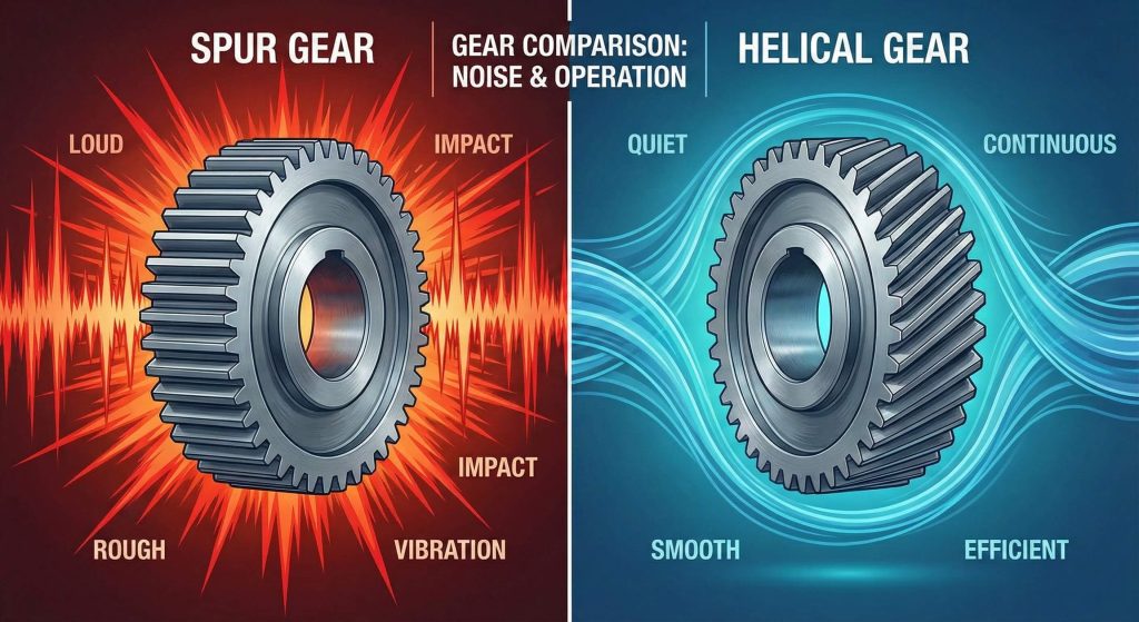
A helical gear wheel is generally better than a spur gear for high-speed or high-load applications due to its superior tooth engagement. While spur gears are cheaper to produce, they lack the smooth transition and load-bearing capacity of the helical design. You will find that the investment in helical technology pays off through reduced maintenance and quieter operation.
Comparing Operational Efficiency
Spur gears are slightly more efficient because they do not produce axial thrust, which can waste a small amount of energy. However, the helical gear’s ability to handle higher RPMs often makes it the more practical choice for modern systems.
Check this out:
- Helical gears run faster without overheating.
- Spur gears are limited by impact noise at high speeds.
- Helical designs offer better long-term reliability.
Cost vs. Performance Analysis
You should choose spur gears for low-speed, budget-friendly applications where noise is not a primary concern. For any mission-critical equipment, the performance advantages of helical gears far outweigh the initial cost difference.
Wait, there is more:
- Helical gears reduce the total cost of ownership.
- Fewer breakdowns mean higher factory productivity.
- Modern manufacturing has lowered the cost of helical units.
Key Takeaway: Choose helical gears for performance-driven systems and spur gears for simple, low-cost machinery.
| Criteria | Spur Gear | Helical Gear |
|---|---|---|
| Noise Floor | High | Very Low |
| Load Limit | Standard | High |
| Manufacturing Cost | Low | Moderate |
The performance gap between these two designs is most apparent in high-speed industrial environments.
How to inspect a helical gear wheel?
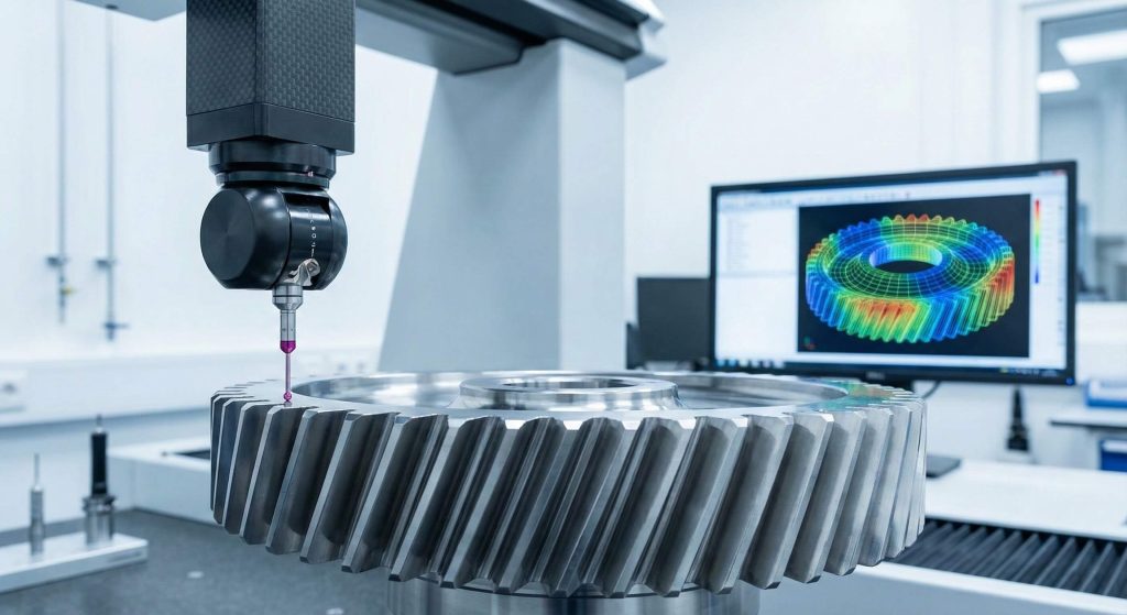
You inspect a helical gear wheel using a combination of visual checks, non-destructive testing (NDT), and geometric measurement tools. Regular inspections help you catch microscopic cracks or surface pitting before they lead to a catastrophic gearbox failure. This proactive approach is the best way to maintain the 100% traceability required for industrial quality standards.
Utilizing Non-Destructive Testing
Magnetic particle and ultrasonic testing are essential for finding internal defects in forged steel gears. You will be able to identify subsurface stress fractures that are completely invisible to the naked eye.
Think about it:
- Early detection prevents sudden machine downtime.
- NDT validates the integrity of the base material.
- Regular checks ensure your safety factors remain high.
Measuring Geometric Accuracy
You must use a Coordinate Measuring Machine (CMM) to verify that the helix angle and tooth profile are within the original design specs. Even a minor deviation in the tooth lead can cause excessive heat and premature wear.
Here is the deal:
- Pitch measurement ensures uniform power flow.
- Profile checks validate the efficiency of the mesh.
- Accurate data allows for better maintenance planning.
Key Takeaway: Rigorous inspection protocols using NDT and CMM tools are vital for ensuring long-term gear reliability.
| Inspection Method | Target Issue | Criticality |
|---|---|---|
| Magnetic Particle | Surface Cracks | High |
| CMM Verification | Geometric Deviation | Moderate |
| Visual Audit | Wear & Pitting | Essential |
Documenting every inspection allows your team to track wear trends and predict the exact remaining service life.
How to maintain your helical gear wheel?
You maintain your helical gear wheel through a rigorous schedule of oil analysis, vibration monitoring, and precise alignment. A well-maintained gear set can last for decades, provided you keep the environment clean and the lubrication film intact. Neglecting these basic steps will lead to rapid tooth degradation and expensive repair bills.
Implementing Vibration Monitoring
Vibration sensors can detect early signs of bearing wear or tooth misalignment long before they become audible to the human ear. You should use this data to schedule maintenance during planned shutdowns rather than reacting to failures.
Check this out:
- Real-time data prevents catastrophic “crashes.”
- Monitoring helps optimize your lubrication schedule.
- Sensors provide a digital record of machine health.
Ensuring Perfect Shaft Alignment
You must check the alignment of your gear shafts regularly to ensure the load is distributed evenly across the entire tooth width. Misalignment causes one end of the tooth to carry all the stress, leading to rapid chipping and failure.
Think about this:
- Laser alignment offers the highest level of precision.
- Proper mounting prevents uneven wear patterns.
- Balanced loads extend the life of both gears and bearings.
Key Takeaway: Proactive maintenance and precise alignment are the keys to achieving the maximum possible service life from your gears.
| Maintenance Task | Benefit | Frequency |
|---|---|---|
| Oil Analysis | Detects Metal Wear | 6 Months |
| Vibration Check | Early Failure Warning | Monthly |
| Alignment Audit | Prevents Uneven Stress | Annually |
Tracking these performance metrics ensures that your equipment remains operational and efficient throughout its life.
Conclusion
This guide has addressed the critical challenges of noise, load capacity, and maintenance that industrial operators face daily. By integrating high-precision helical gears, you resolve the problems of mechanical vibration and unexpected downtime. GearAide is dedicated to providing reliable transmission components through genuine manufacturing and engineering-focused communication. We help your equipment run longer with fewer breakdowns and absolute traceability. To optimize your drive systems and reduce operational risks, contact us today.
FAQ
Are helical gear wheels efficient?
Yes, they typically offer 90-99.5% efficiency. Their rolling contact design minimizes energy loss while handling high torque loads.
Can helical gear wheels run at high speeds?
Yes, they are the preferred choice for high-speed rotation. Their gradual engagement prevents the noise and vibration that limit spur gears at high RPMs.
How do you handle helical gear wheel axial load?
You must use thrust bearings or a double helical design. These solutions neutralize the “screwing” force generated by the angled teeth.
What defines a helical gear wheel’s capacity?
Its capacity is defined by the material grade and the helix angle. Higher contact ratios allow for significantly more power transmission than straight gears.
Why choose a helical gear wheel over a spur gear?
You choose it for noise reduction and load density. It is the superior technical solution for any application requiring smooth and powerful operation.