Helical gear units are high-capacity mechanical transmission systems that use angled teeth to provide smooth torque delivery and extreme stability for heavy machinery. Plant managers frequently encounter significant challenges with excessive vibration and premature component failure when using standard gear sets in high-speed applications. These issues lead to unplanned downtime and high replacement costs while also creating safety hazards for personnel on the factory floor. Here is the deal. Transitioning to a more robust transmission architecture is the primary method for reclaiming lost efficiency and protecting capital equipment. Robust helical gear units rely on decades of proven reliability to maintain equipment stability under extreme loads.
1. What are helical gear units in modern machinery?
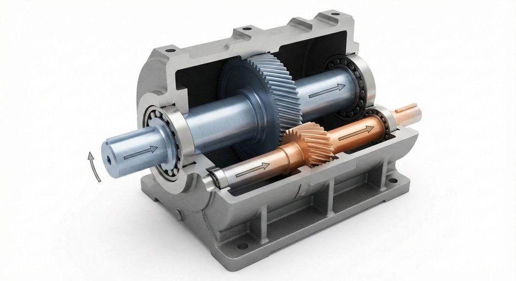
Understanding the parallel axis arrangement
These units feature a design where the input and output shafts remain parallel to ensure a streamlined flow of mechanical energy. This layout allows for a compact footprint while maintaining high structural integrity during heavy operation. But wait, there is more. You can easily integrate this arrangement with standard industrial motors and various machine frames.
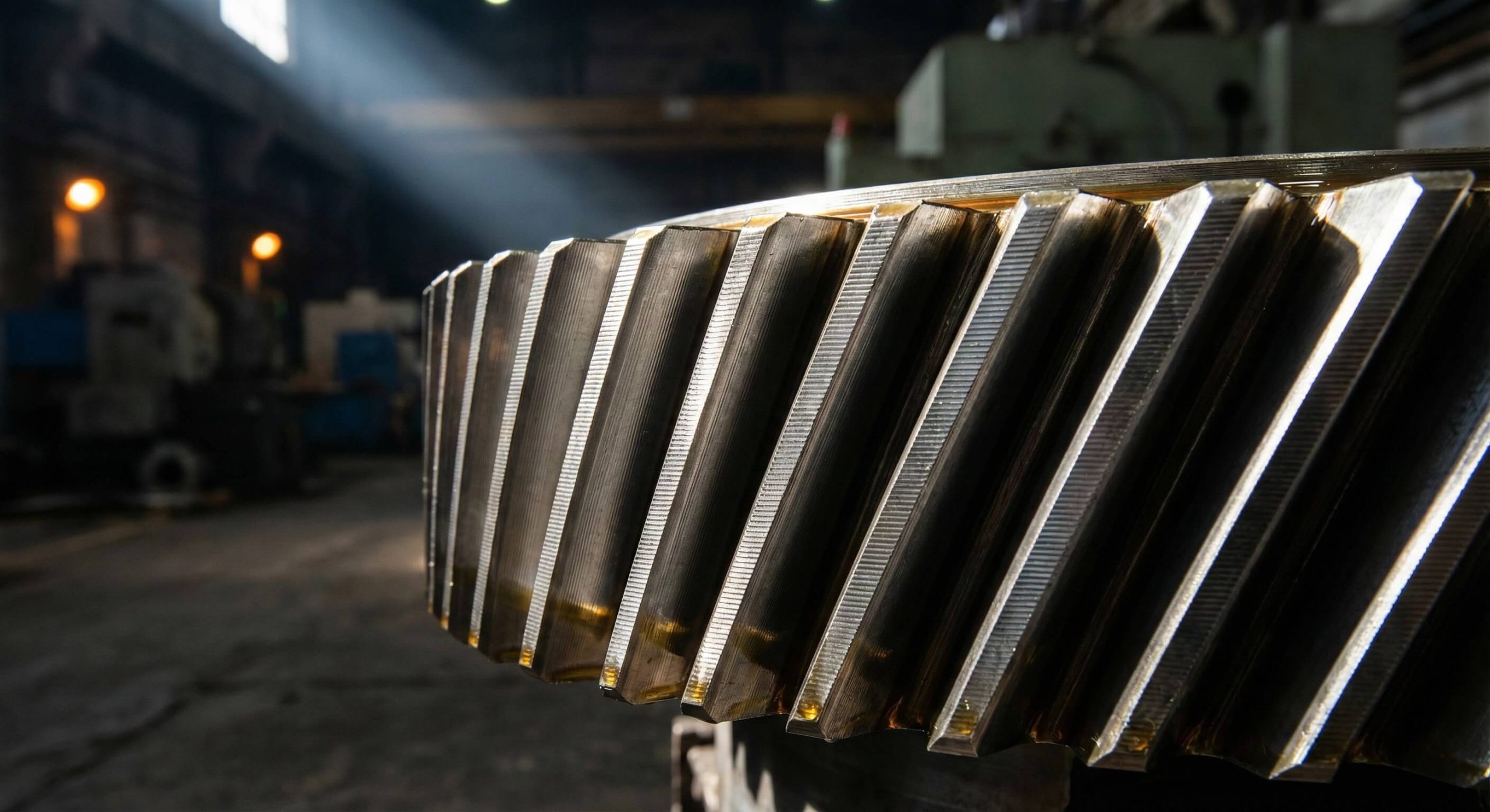
The function of helical tooth geometry
The defining characteristic of these systems is the use of angled teeth that follow a helical path around the gear axis. This geometry ensures that the gears engage gradually, which distributes the load across a larger surface area than straight-cut teeth. You might be wondering how this affects performance, but the result is a much higher contact ratio.
Components of the gear assembly
Every unit consists of a high-strength housing, precision-ground gears, and heavy-duty bearings to support the internal shafts. Robust seals prevent lubrication leakage and protect your internal components from environmental contaminants like dust or moisture. This is where it gets interesting. These parts work together to provide reliable speed reduction and torque multiplication.
- Parallel shaft alignment for efficiency.
- Helical tooth profiles for smooth transitions.
- High-grade bearings for axial support.
- Specialized sealing for environmental protection.
Key Takeaway: Understanding the parallel arrangement and helical geometry helps you select the right architecture for space-constrained industrial environments.
| Feature | Specification | Layout Type |
|---|---|---|
| Tooth Type | Helical (Angled) | Parallel Shaft |
| Ratio Range | 1:3 to 1:22,000 | Compact |
| Material | Case-Hardened Steel | Robust |
The mechanical architecture of these units provides the necessary foundation for high-torque applications requiring long-term precision.
2. How do helical gear units outperform standard gear types?
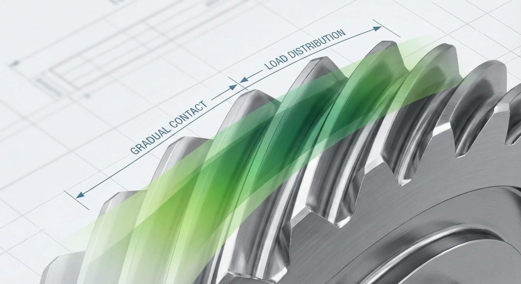
Helical gear units outperform spur gears because their angled teeth engage gradually, eliminating the harsh impact associated with straight-cut designs. This gradual engagement reduces shock loading on the motor and extends the operational life of your entire drive train. Here is the deal. Because the engagement is progressive, mechanical stress is distributed more evenly across the material face.
Impact of gradual tooth engagement
Standard spur gear designs experience sudden contact across the entire tooth width at once. In contrast, helical profiles enter the mesh at a single point and slide into full contact. But wait, there is more. This behavior prevents the momentary deceleration and vibration spikes common in lower-quality transmission sets.
Load distribution and surface area
Angled teeth provide a significantly larger surface area for contact within the same physical gear width. This increased contact area allows the unit to carry heavier loads without requiring you to increase the footprint of the machinery. You might be wondering if this adds weight, but the efficiency gains usually offset any minor mass differences.
- Gradual mesh entry reduces shock.
- Higher surface area supports heavier loads.
- Multiple teeth in contact simultaneously.
- Enhanced durability for 24/7 operations.
Key Takeaway: Choosing helical designs over spur gears provides you with higher load capacities and a more resilient transmission system.
| Parameter | Spur Gear | Helical Gear Unit |
|---|---|---|
| Contact Type | Impact/Line | Gradual Surface |
| Surface Area | Moderate | High |
| Load Sharing | Single Tooth | Multiple Teeth |
The transition from spur to helical designs represents a fundamental upgrade in how your machinery handles mechanical stress.
3. Why do helical gear units provide a quieter workspace?
Helical gear units reduce noise by utilizing sliding contact mechanics that eliminate the high-pitched whine common in industrial environments. The angled teeth engage in a continuous rolling motion, which dampens acoustic energy before it can radiate through the housing. This is where it gets interesting. Reducing noise levels is not just about comfort; it indicates a reduction in damaging mechanical friction.
Acoustic dampening through angled contact
The geometry of the gears shifts the frequency of vibration away from the resonant frequencies of the machine frame. By avoiding these resonance points, the unit operates with a much lower decibel rating than traditional drives. But wait, there is more. You can typically achieve noise reductions of up to 15 decibels compared to standard gearboxes.
Managing impulse forces and chatter
Because the engagement is progressive, the impulse forces that cause “gear chatter” are virtually eliminated. This leads to a smoother rotation that benefits sensitive downstream processes in your production line. You might be wondering about bearing life, and lower impulse forces definitely extend the time between service intervals.
- Sliding contact minimizes acoustic output.
- Frequency shifting avoids frame resonance.
- Elimination of chatter during operation.
- Enhanced operator safety through quietness.
Key Takeaway: Implementing these units allows you to maintain a safer, quieter workplace while improving the precision of your machinery.
| Metric | Spur Gears | Helical Units |
|---|---|---|
| Noise (dB) | 85-95 dB | 70-75 dB |
| Vibration | High | Low |
| Mesh Type | Impact | Sliding |
A quieter operation usually signals a well-aligned and highly efficient mechanical system that wastes less energy as sound.
4. Can helical gear units handle extreme industrial torque?
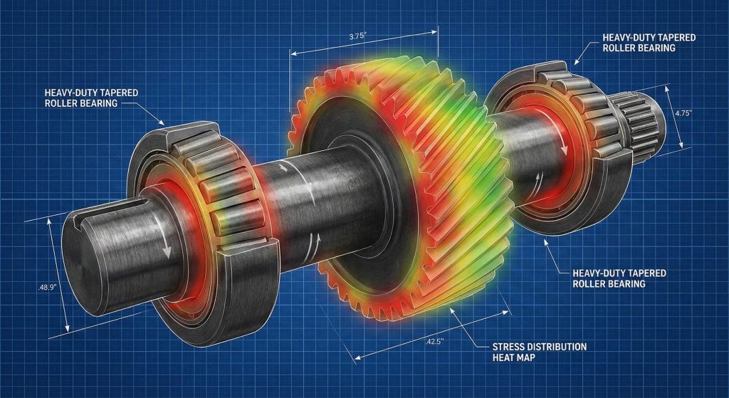
High-capacity helical gear units are specifically designed to manage extreme torque loads by utilizing carburized and quenched steel. These units can handle output torques ranging from 60 Nm up to 13,600 Nm for massive industrial applications. Here is the deal. The ability to scale torque performance across different frame sizes makes them highly versatile for your facility.
Axial thrust and bearing support
Angled teeth generate lateral forces known as axial thrust during the power transmission process. Heavy-duty taper roller bearings are utilized within the housing to counteract these forces and maintain perfect shaft alignment. But wait, there is more. Modern bearing technology allows you to manage these loads effortlessly even at high rotational speeds.
Materials and scalability for torque
Manufacturers use high-grade steel that undergoes specialized heat treatment to ensure surface hardness and core toughness. This metallurgical balance prevents tooth deformation under shock loads while resisting surface pitting. You might be wondering about frame sizes, but you can select from a wide range to match your specific torque needs.
- Taper roller bearings for thrust.
- Carburized steel for tooth hardness.
- Torque capacity up to 13,600 Nm.
- High-impact shock load resistance.
Key Takeaway: You can rely on these units for heavy-duty applications where standard transmission components would typically fail under load.
| Component | Material | Torque Limit |
|---|---|---|
| Gear Teeth | Quenched Steel | 13,600 Nm |
| Bearings | Tapered Roller | High Axial |
| Housing | Grey Cast Iron | Structural |
The combination of advanced metallurgy and robust bearing support enables these units to thrive in the most demanding environments.
5. What mounting options exist for your helical gear units?
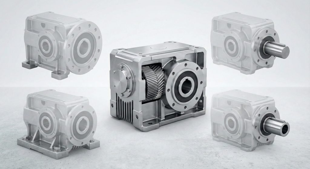
The most common mounting options include foot-mounted, flange-mounted, and foot-flange configurations to provide you with maximum installation flexibility. Foot-mounted versions allow the unit to sit securely on a solid floor or machine base for high-stability applications. This is where it gets interesting. Your choice of mounting depends entirely on the existing architecture of your production equipment.
Integrating flange and shaft options
Flange-mounted configurations allow you to attach the gearbox directly to the machine housing or an agitator tank. This saves space and ensures perfect alignment between the drive unit and the driven component. But wait, there is more. Eliminating external couplings through flange mounting can also reduce the overall maintenance points of your system.
Solid and hollow shaft orientations
You can choose between solid output shafts for pulleys and hollow shafts for direct shaft mounting. Solid shafts are preferred for high-torque transfers where a robust mechanical connection is required for your drive. You might be wondering about precision, and using a shrink disc on a hollow shaft can provide a zero-backlash connection.
- Foot-mounted for floor stability.
- Flange-mounted for compact setups.
- Solid shafts for pulley drives.
- Hollow shafts for direct mounting.
Key Takeaway: Diverse mounting configurations give you the flexibility to integrate high-performance gearing into almost any existing machine layout.
| Mounting Type | Primary Benefit | Common Use |
|---|---|---|
| Foot | High Stability | Conveyors |
| Flange | Space Saving | Mixers |
| Foot-Flange | Versatility | Custom OEM |
Selecting the correct mounting style simplifies the installation process and ensures the long-term structural integrity of your drive.
6. How efficient are high-performance helical gear units?
High-quality helical gear units achieve efficiency ratings between 94% and 96% by minimizing friction losses at each gear mesh. This performance level is significantly higher than that of a worm gear, making helical systems the preferred choice for energy-conscious facilities. Here is the deal. Higher efficiency translates directly into lower energy bills and reduced thermal stress for your equipment.
Minimizing power loss through precision
Precision surface finishes and optimized tooth profiles ensure that the gears roll over each other with minimal sliding friction. This reduces the amount of power converted into waste heat during 24/7 operation. But wait, there is more. Keeping the system cool through high efficiency prevents the premature breakdown of your lubrication oil.
Lubrication and thermal management
Advanced synthetic lubricants and specialized seals work together to keep the internal environment frictionless and clean. Proper lubrication ensures that the metal surfaces never touch, even when you operate under extreme pressure. You might be wondering if oil type matters, but synthetic options provide the best thermal stability for your high-speed runs.
- Efficiency ratings up to 96 percent.
- Low heat generation during use.
- Precision grinding reduces friction.
- Major energy savings over long cycles.
Key Takeaway: Investing in high-efficiency units reduces your operational costs and helps you meet modern industrial sustainability goals.
| System Stage | Efficiency % | Heat Profile |
|---|---|---|
| Single Stage | 97-98% | Negligible |
| Multi-Stage | 94-96% | Low |
| Competing Worm | 50-90% | High |
The mechanical superiority of helical gearing ensures that the maximum amount of motor power reaches your output shaft.
7. Where do industries utilize specialized helical gear units?
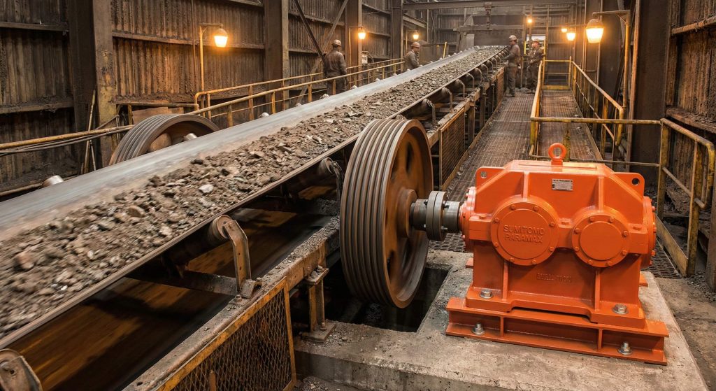
Helical gear units are used across diverse sectors including material handling, automotive manufacturing, and chemical processing. Their robust nature makes them ideal for the constant start-stop cycles found in logistics centers and baggage handling systems. This is where it gets interesting. These units provide the reliability needed to keep your global supply chains moving without interruption.
Logistics and conveyor drive systems
Conveyor systems rely on high-torque output and smooth speed reduction to transport heavy goods across your factory floor. Helical systems provide the durability to handle these loads while maintaining low noise for nearby workers. But wait, there is more. The compact design allows these drives to be tucked away under conveyor frames with ease.
Applications in mining and wind power
In harsh environments like mining sites or wind turbines, the units are protected by specialized coatings and heavy-duty seals. They must withstand extreme dust, moisture, and fluctuating temperatures while transmitting massive power. You might be wondering about remote service, but the long life of these units saves significant costs in difficult locations.
- Logistics and conveyor drives.
- Plastics and textile machinery.
- Wind turbine yaw and pitch.
- Heavy-duty mining excavation.
Key Takeaway: You can apply these units in almost any industrial environment to improve reliability and mechanical performance.
| Industry | Primary Need | Helical Benefit |
|---|---|---|
| Logistics | Torque | Durability |
| Wind Power | Reliability | Weather Sealing |
| Textiles | Smoothness | Speed Control |
The versatility of these gearboxes makes them a universal solution for your modern industrial power transmission challenges.
8. How should you maintain helical gear units for long life?
Maintaining helical gear units requires a consistent schedule of lubrication intervals and vibration monitoring to prevent metal-on-metal contact. Regular oil analysis is the most effective way for you to identify internal wear before a catastrophic failure occurs. Here is the deal. Clean oil is the lifeblood of your transmission system and must be kept free of contaminants.
Lubrication schedules and oil quality
Over time, gear oil loses its viscosity and its ability to protect the tooth surfaces from friction and heat. Replacing the oil every 10,000 hours of operation ensures that your gear set remains fully protected. But wait, there is more. You should always use the specific oil grade recommended for your operational temperature range.
Monitoring vibration and housing temperature
Vibration probes and thermal sensors can track the health of your gearbox by detecting subtle changes in operational patterns. An increase in temperature or a shift in vibration frequency usually indicates a bearing is reaching its end of life. You might be wondering about detection, but catching these issues early allows for planned maintenance during scheduled downtime.
- Oil changes every 10,000 hours.
- Quarterly vibration checks.
- Annual oil analysis for metal.
- Thermal monitoring of housing.
Key Takeaway: Regular maintenance protects your capital investment and prevents the high costs associated with unplanned production stops.
| Task | Frequency | Goal |
|---|---|---|
| Visual Check | Weekly | Leak Detection |
| Oil Analysis | Annually | Wear Tracking |
| Full Overhaul | 30,000 Hours | Life Extension |
A proactive maintenance strategy ensures that your equipment reaches its full design life of 20,000 to 30,000 hours.
9. Can you customize helical gear units for specific OEMs?
Yes, manufacturers can customize helical gear units by modifying output shaft dimensions, material specifications, and mounting orientations to fit unique machinery. This level of vertical integration allows for the seamless replacement of legacy parts or the creation of new drive architectures. This is where it gets interesting. You don’t have to settle for a standard product if your machine has non-standard requirements.
Engineering custom shaft dimensions
You can specify custom shaft lengths, splines, or keyways to match your existing couplings or pulleys without expensive modifications to your machine. This flexibility is essential for original equipment manufacturers (OEMs) who want to differentiate their products. But wait, there is more. Custom material selections can also be made for units operating in corrosive environments.
Reverse engineering for legacy machines
If you are working with an older system where parts are no longer available, experts can replicate and improve the original design. This process involves measuring the original gears and applying modern heat treatments to increase durability. You might be wondering about accuracy, and CAD modeling ensures a perfect fit for your legacy equipment.
- Custom shaft geometry and splines.
- Material upgrades for environments.
- Reverse engineering legacy designs.
- Tailored mounting for unique frames.
Key Takeaway: Leveraging customization options allows you to optimize your machine performance and simplify your industrial supply chain.
| Customization | Type | Benefit |
|---|---|---|
| Shaft Geometry | Dimensional | Direct Fit |
| Material Spec | Metallurgical | Life Extension |
| Sealing | Environmental | Washdown Proof |
Customization ensures that the gear unit serves the specific needs of your application rather than forcing a compromise.
10. What is the future of helical gear units in automation?
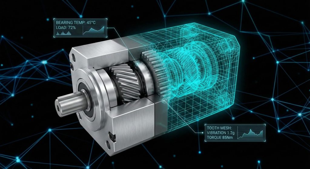
The future of helical gear units in automation involves integration with high-precision servo motors and the use of lightweight high-performance alloys. As robotics become more prevalent, the demand for low-backlash and high-dynamic-response gearboxes continues to grow. Here is the deal. Gearing is evolving from simple speed reduction into a critical component of your precision motion control systems.
Integration with robotic servo motors
Servo-geared motors use helical stages to provide the smooth, high-torque movement necessary for robotic arms and automated picking systems. The low noise and vibration of helical designs are essential for maintaining the accuracy of your automated systems. But wait, there is more. New sensor-integrated gearboxes can now communicate their health directly to your central control system.
Material innovations and weight reduction
Manufacturers are experimenting with aluminum alloys and new composite materials to reduce the mass of the gear housing. Lighter units require less energy to move and can be used on mobile robotic platforms where every kilogram matters. This is where it gets interesting. These weight savings are achieved without you having to sacrifice torque capacity or reliability.
- Integration with servo drives.
- IoT sensors for maintenance.
- Lightweight robotic housings.
- Refined high-speed tooth profiles.
Key Takeaway: Staying ahead of these automation trends allows you to build more competitive and intelligent production systems.
| Trend | Technology | Impact |
|---|---|---|
| Smart Gears | IoT Sensors | Zero Downtime |
| Lightweighting | New Alloys | Higher Mobility |
| Precision | Servo-Geared | System Accuracy |
Innovation in materials and digital integration ensures that helical gearing remains the backbone of your modern industrial automation.
Conclusion
Helical gear units represent the pinnacle of mechanical power transmission, offering a unique combination of high efficiency, extreme durability, and quiet operation. By moving beyond the limitations of standard gears, you gain a transmission system capable of handling the most demanding industrial loads while reducing energy costs and maintenance requirements. Our vision is to provide the global engineering community with robust, traceable, and innovative gear solutions that drive industrial progress forward. To experience the stability and precision of a custom-engineered transmission system, contact us today.
Frequently Asked Questions
Q1: Can I replace a spur gear with a helical gear unit in my existing machine?
Yes, replacement is possible but requires verifying the axial thrust capacity of your current bearings. Helical gears generate lateral forces that straight-cut gears do not, so the housing and shafts must support the redirected load.
Q2: What is the best lubrication for a high-speed helical gear unit?
Synthetic gear oils are generally superior for high-speed applications. They offer better thermal stability and a more consistent viscosity index than mineral oils over long operational cycles, protecting the gear teeth more effectively.
Q3: Can I run a helical gear unit in both directions?
Most units are designed for bi-directional rotation. However, you must ensure that the internal lubrication system, such as an oil pump or splash feed, is compatible with reverse rotation to prevent dry-running.
Q4: What is the typical service life of a well-maintained gear set?
Industrial-grade units often achieve a service life of 20,000 to 30,000 hours. This longevity depends heavily on maintaining clean oil, using the correct lubricants, and operating within the specified torque limits of the unit.
Q5: How do I know if my gear unit is overheating?
Surface temperatures should generally remain below 80 degrees Celsius. If the housing is too hot to touch or you notice a burnt smell in the oil, the unit is likely overloaded or the lubrication is insufficient.