
What is a Girth Gear?
A girth gear is a large-diameter external ring gear mounted to the circumference of rotating cylindrical equipment such as cement kilns, ore processing mills, and industrial dryers. Yantong Tech manufactures girth gears in monolithic or segmented configurations, with controlled tooth geometry, verified heat treatment integrity, and machined mounting surfaces to ensure reliable drive engagement and long service intervals under continuous thermal cycling and shock loads.
- Outer diameter range 800–8000 mm; module m8–m40; manufactured as single-piece castings or multi-segment bolted assemblies for transportation and field installation
- Tooth profile accuracy DIN 8–10; hobbing, milling, or planing followed by profile inspection to confirm involute form and pitch consistency for smooth pinion meshing
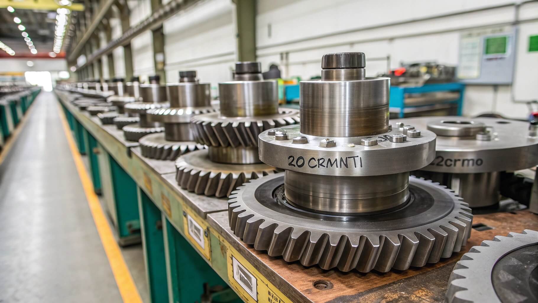
- Material options include cast steel (GS-52, GS-60), forged alloy steel (42CrMo4, 34CrNiMo6), or ductile iron (GGG-50, GGG-70) depending on load, thermal exposure, and maintainability requirements
- Heat treatment and stress relief controlled to minimize distortion and internal residual stress; hardness and microstructure verified through metallographic examination and hardness mapping
Engineering Characteristics and Operational Advantages
Design features enabling predictable torque transmission, field serviceability, and extended operational life in high-temperature rotating equipment
Segmented Construction for Large Diameters
Girth gears exceeding 2500 mm OD typically manufactured in 2–6 arc segments with precision-machined mating flanges and bolt holes, enabling road transport and on-site assembly without crane capacity limitations or furnace heat treatment size constraints.
Thermal Stability and Controlled Distortion
Stress-relief annealing after rough machining and final normalization or quench-and-temper cycles reduce residual stress and thermal distortion during operation; dimensional verification at elevated temperature available for kilns operating above 200°C shell temperature.
Field-Replaceable Design and Maintenance Access
Bolted segment joints and removable mounting hardware permit in-place replacement of worn or damaged sections without full equipment disassembly; gear tooth refurbishment via portable milling or welding repair supported by documented dimensional records.
Technical Specifications and Manufacturing Capacity
Comprehensive parameter overview for rotary kiln, ball mill, and industrial dryer girth gear applications
| Item | Specification Range | Remarks |
|---|---|---|
| Outer Diameter | 800 mm – 8000 mm | Monolithic up to 2500 mm; segmented construction for larger sizes |
| Module | m8 – m40 | Coarse pitch for heavy load and shock resistance |
| Number of Teeth | 60 – 800 | Determined by diameter, module, and drive ratio |
| Face Width | 100 mm – 800 mm | Proportional to module and load capacity requirements |
| Tooth Accuracy | DIN 8 – DIN 10 | Achievable via hobbing, milling, or planing with profile verification |
| Materials | GS-52 / GS-60 cast steel 42CrMo4 / 34CrNiMo6 forged steel GGG-50 / GGG-70 ductile iron |
Material selection based on load, temperature, and weldability |
| Heat Treatment | Normalizing / Quench & Temper / Stress Relief Annealing | Controlled to achieve target hardness and toughness balance |
| Hardness Range | HB 190–280 (cast steel) HB 240–320 (forged steel) |
Uniform hardness distribution verified across tooth flank |
| Mounting Configuration | Bolt-on segments / Shrink-fit rings / Welded assemblies | Design depends on kiln diameter, shell thickness, and maintenance philosophy |
| Inspection | Ultrasonic testing / Magnetic particle inspection / Hardness mapping / Tooth profile measurement | Full inspection data package provided with shipment |
Custom Manufacturing and Field Service Capability
Four core competencies supporting new equipment, retrofit projects, and emergency replacement for rotary kiln and mill operations

Reverse Engineering & Dimensional Replication
Worn girth gears measured via portable CMM or laser scanning; tooth profile, pitch diameter, and bolt hole patterns replicated from site data; material composition identified via spectroscopy for equivalent specification.
Heavy Machining & Assembly
Vertical turning lathes and CNC gear hobbers up to 8-meter diameter capacity; segmented gears machined with match-mark flanges and dowel pin alignment for field assembly; final inspection performed in assembled configuration.
Material Selection & Heat Treatment
Cast or forged material options evaluated based on load spectrum, thermal cycling, and weldability for field repair; normalizing and tempering cycles documented with furnace charts; hardness uniformity verified via Brinell indentation mapping.
Non-Destructive Testing & Documentation
Ultrasonic inspection for internal casting defects; magnetic particle testing for surface and near-surface cracks; dimensional report with tooth profile deviation and runout data; material traceability and mechanical test results archived by serial number.
Manufacturing Process: From Material Verification to Field-Ready Girth Gear
Seven controlled stages ensuring dimensional integrity, material soundness, and assembly readiness for rotary equipment installation

Material Procurement & Foundry Inspection
Cast steel or ductile iron blanks procured from qualified foundries with mill certificates; chemical composition, tensile strength, and impact toughness validated against specification; ultrasonic inspection performed to confirm freedom from internal porosity or inclusions before machining release.
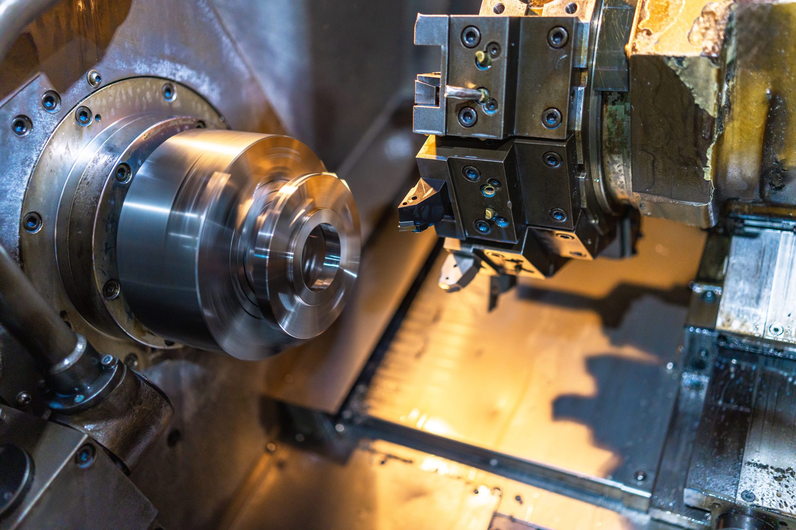
Rough Turning & Bore Machining
Vertical turning lathe machines outer diameter, inner bore, and mounting faces to near-final dimensions; datum surfaces established for subsequent tooth cutting and segment flange machining; first-piece dimensional check confirms fixture setup and toolpath accuracy.

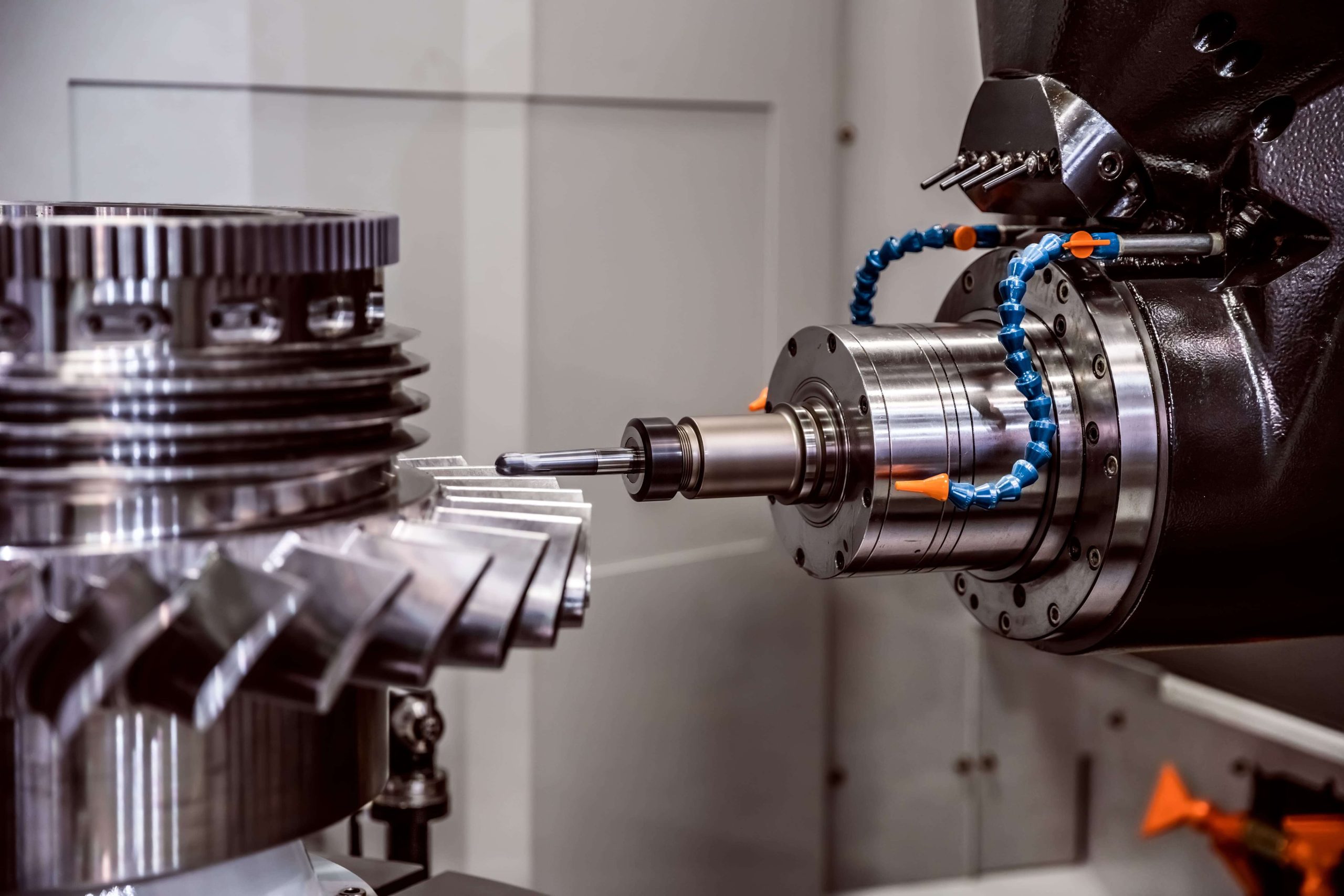
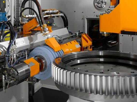
Tooth Cutting (Hobbing, Milling, or Planing)
CNC gear hobber or heavy-duty milling machine cuts teeth to specified module, pressure angle, and helix angle; cutting parameters controlled to achieve surface finish Ra 6.3–12.5 μm; in-process checks monitor tooth thickness and profile form at multiple angular positions around circumference.
Heat Treatment & Stress Relief
Normalizing or quench-and-temper heat treatment cycle applied to achieve target hardness (HB 190–320 depending on material and specification); stress-relief annealing performed after rough machining and again after final machining if dimensional stability is critical; furnace cycle charts and hardness test results documented for traceability.

Finish Machining & Segment Flange Preparation
Mounting surfaces, bolt holes, and segment mating flanges machined to final tolerance (typically IT9–IT11 for bolt holes, Ra 3.2 for mating faces); dowel pin holes drilled for rotational alignment; edges deburred to prevent stress concentration and handling damage during transport and installation.
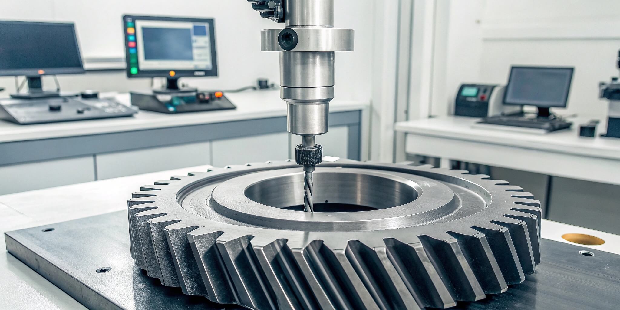
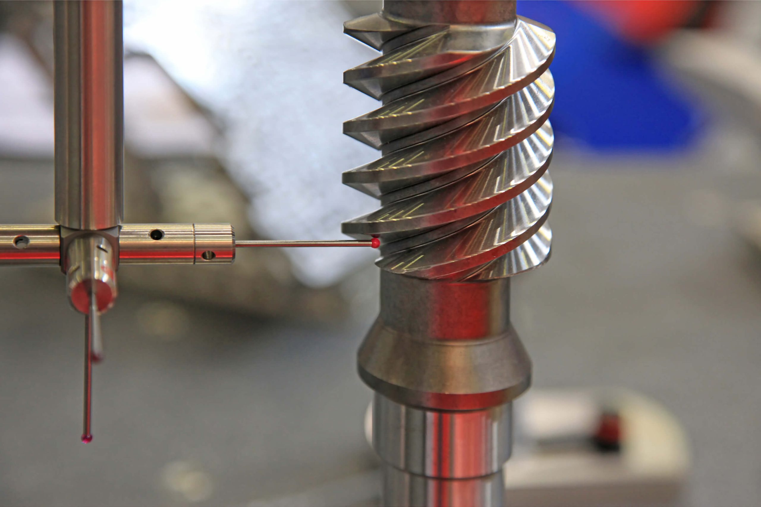
Dimensional Inspection & Tooth Profile Verification
Gear measurement instruments (portable or stationary) record tooth profile deviation, pitch variation, and runout; CMM or laser tracker verifies bolt hole pattern and segment flange geometry; all data compared to drawing tolerance and archived in inspection certificate; non-conformances flagged for corrective machining or engineering disposition.
Assembly Verification & Preparation for Shipment
Segmented gears trial-assembled to verify flange fit and dowel pin alignment; assembly torque specification and installation sequence documented in technical manual; anti-rust coating applied to machined surfaces; segments packaged in protective crates with lifting lug locations and center-of-gravity marks for safe handling at installation site.
Quality Control and Inspection Protocol
Five-stage verification system ensuring material integrity, dimensional accuracy, and installation readiness for critical rotating equipment
Material Verification & Foundry Acceptance
Mill certificates validated against purchase specification; chemical composition confirmed via optical emission spectrometry (OES); tensile and impact test coupons evaluated per ASTM or EN standards; ultrasonic inspection performed on castings to detect internal porosity, shrinkage cavities, or non-metallic inclusions before machining release.
Dimensional Inspection at Key Machining Stages
First-piece approval after rough turning confirms datum surface accuracy and fixture setup; in-process checks during tooth cutting monitor module, pressure angle, and tooth thickness at multiple circumferential positions; final machining verified via CMM or laser tracker for bolt hole pattern, mounting face flatness, and segment flange geometry.
Tooth Profile & Pitch Measurement
Portable or stationary gear measurement instruments record tooth profile deviation, pitch variation, helix angle (if applicable), and runout relative to bore or mounting datum; data compared to DIN 8–10 tolerance class or customer-specified limits; non-conformances evaluated for corrective machining or engineering disposition with root cause analysis.
Heat Treatment Validation & Hardness Mapping
Furnace cycle charts archived with time-temperature profiles and soak duration; hardness measured at tooth flank, tooth root, and core via Brinell or Rockwell methods; hardness uniformity confirmed across multiple teeth and axial positions; metallographic examination performed on representative samples to verify grain structure, phase composition, and freedom from quench cracks or decarburization.
Non-Destructive Testing & Final Documentation
Magnetic particle inspection (MPI) or liquid penetrant testing (PT) applied to machined surfaces and weld zones (if applicable) to detect surface-breaking cracks; ultrasonic testing (UT) repeated after heat treatment to confirm continued freedom from internal defects; final inspection certificate compiled with material traceability, dimensional data, hardness results, NDT reports, and segment assembly instructions.
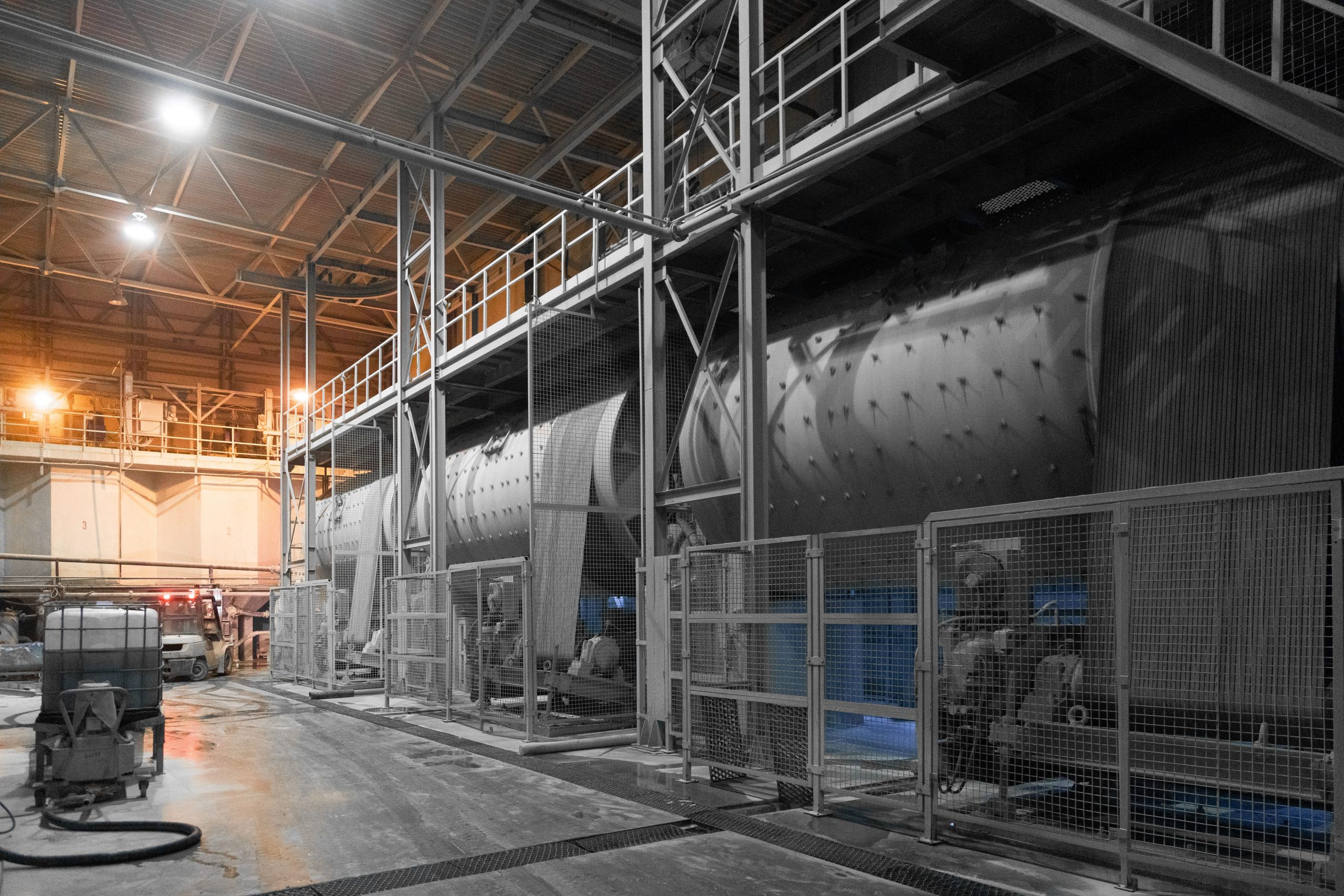
Applications and Industry Integration
Girth gears enabling reliable continuous rotation in high-temperature, high-load industrial processes across six core sectors


Certifications and Compliance Standards
Quality management systems and material traceability supporting international procurement and project specifications
ISO 9001:2015
IATF 16949 Methods
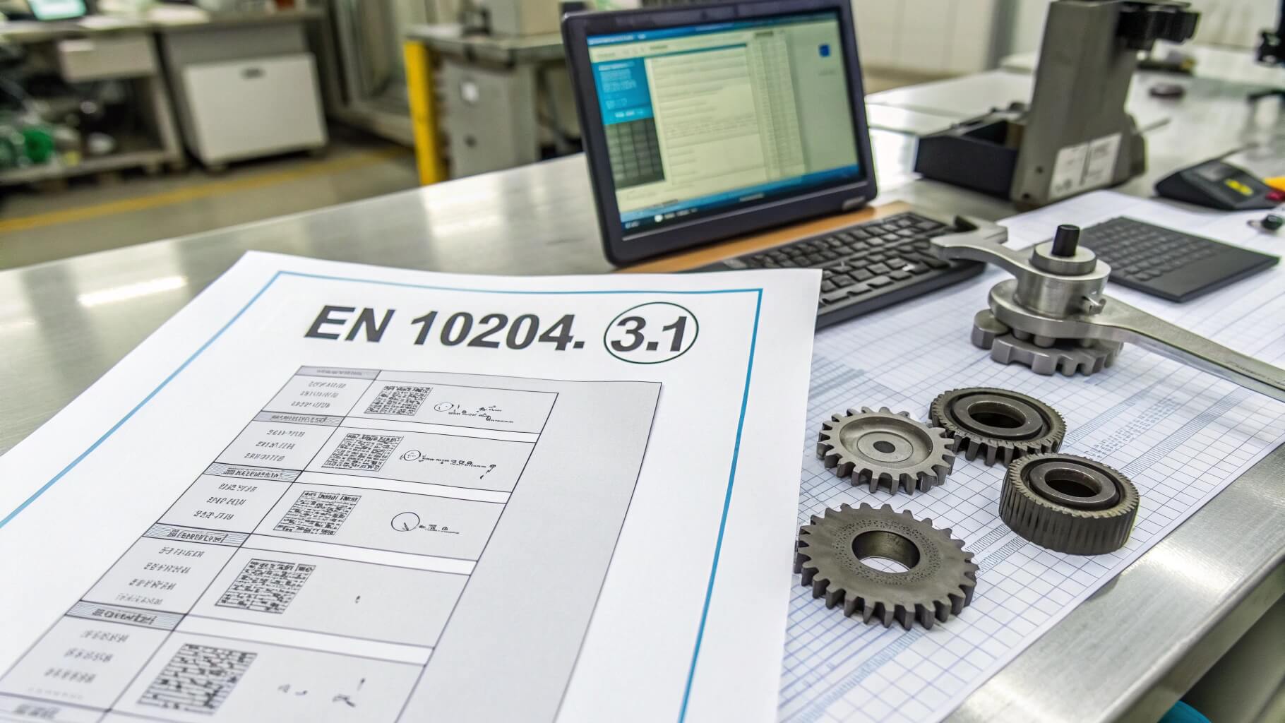
Material Traceability (EN 10204 3.1)
RoHS / REACH Compliance
Material Selection and Heat Treatment Strategy
Material choice and thermal processing directly influence girth gear load capacity, thermal stability, and field repairability. Yantong Tech evaluates material options based on operating temperature, shock load severity, corrosion exposure, and customer maintenance philosophy, with full heat treatment traceability and mechanical property validation.


Engineering Collaboration and Field Support
Technical services supporting new installations, retrofit projects, and emergency replacement for rotary kiln and mill operations
- Reverse engineering from site measurements: dimensional replication from worn girth gears using portable CMM, laser scanning, or manual measurement; tooth profile reconstruction and material identification via spectroscopy; installation drawing preparation with segment layout and bolt torque specifications.
- Load analysis and material selection guidance: drive torque and shock load evaluation based on equipment capacity and duty cycle; material recommendation (cast steel vs. forged steel vs. ductile iron) considering thermal exposure, maintenance philosophy, and budget constraints; segment joint design optimization for bolt preload and flange stress distribution.
- Field installation support and alignment procedures: segment assembly sequence documentation with dowel pin alignment and bolt tightening torque schedules; mounting surface inspection criteria and shimming recommendations for runout control; pinion mesh adjustment guidelines to achieve proper tooth contact pattern and backlash.
- Maintenance documentation and spare parts planning: wear inspection criteria and tooth thickness monitoring recommendations; lubrication specifications for open gear drives (viscosity, application frequency, contaminant control); preventive maintenance schedules and expected service life estimates based on operating conditions and historical performance data.
What Our Clients Say
Trusted by cement producers, mining operators, and heavy industry maintenance teams across three continents
Our cement kiln required a replacement girth gear with 4.2-meter outer diameter after the original developed tooth wear. Yantong Tech reverse-engineered from our site measurements, fabricated three segments with precise flange alignment, and delivered complete installation documentation. The gear has been running smoothly for 18 months with no issues.
We needed an emergency replacement girth gear for our SAG mill after a tooth fracture. Yantong provided material selection guidance, expedited manufacturing, and coordinated with our installation contractor. The comprehensive NDT reports and heat treatment data gave us confidence in the quality. Very professional engineering support throughout.
Yantong Tech supplied girth gear segments for our copper concentrator ball mill modernization project. The gear teeth were pre-machined to tight tolerances, segment flanges aligned perfectly during field assembly, and all documentation was complete for our quality audit. Good communication and realistic lead times made the project go smoothly.
Why Plant Engineers and Project Managers Choose Yantong Tech for Girth Gears
Four core competencies supporting rotary equipment reliability, emergency replacement readiness, and long-term maintenance planning
Large-Diameter Machining Capability
Vertical turning and hobbing capacity up to 8-meter diameter; segmented construction expertise for field assembly; precision flange machining for bolt-up alignment without line boring or shimming at installation site.
Material & NDT Validation
Cast steel, forged steel, and ductile iron options with EN 10204 Type 3.1 certificates; ultrasonic and magnetic particle testing by Level II certified inspectors; heat treatment traceability with furnace cycle documentation and hardness mapping reports.
Reverse Engineering & Field Support
Worn gear replication from site measurements without original drawings; installation procedure documentation with torque specifications and alignment tolerances; remote technical consultation for troubleshooting and preventive maintenance guidance.
Realistic Lead Time & Emergency Response
Transparent manufacturing schedules with milestone tracking; expedited production available for unplanned failures; segmented design enables partial replacement if only specific arc sections are damaged, reducing downtime and cost versus full ring replacement.
Packaging and Export Logistics
Four-stage protection protocol ensuring gear segment integrity during international transport and field handling

Corrosion Prevention & Sealed Protection
Surfaces are treated with rust-inhibiting oil or VCI protection depending on transit duration and climate, and each gear is sealed in PE bags with desiccant to control humidity from factory loading to overseas delivery.
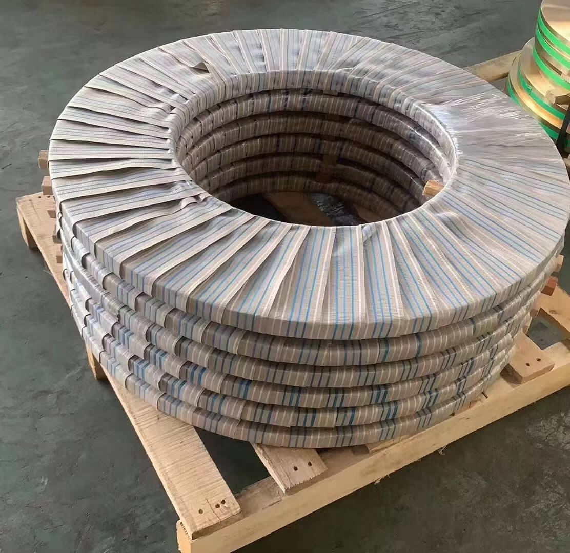
Tooth Edge Protection & Anti-Impact Support
Large gears are positioned on rigid pallets or supports that bear the weight, while tooth edges are wrapped or cushioned to avoid contact damage during loading and transport. Wrapping also helps reduce dust and moisture exposure before crating.
Reinforced Crating & Export-Ready Loading
Gears are secured in reinforced plywood crates with proper corner strength and lifting points, and crate dimensions are planned for safe forklift engagement and container loading according to destination requirements.
Frequently Asked Questions About Girth Gears
Quick answers to common technical and commercial inquiries for rotary equipment girth gear replacement projects
Technical Questions
Commercial Questions
How to Start Your Girth Gear Replacement Project
A transparent seven-step process from initial inquiry to field installation support and ongoing maintenance guidance
Submit Equipment Information & Requirements
Provide equipment type (kiln, mill, dryer), outer diameter, current gear condition (worn, damaged, missing), operating temperature, drive power, and photos if available. If original drawings unavailable, we arrange site visit or remote measurement guidance for dimensional data collection.
Initial Contact & Data Gathering
Equipment assessment and measurement planning
Engineering Review & Design
Reverse engineering or specification confirmation
Dimensional Verification & Material Selection
Our engineers analyze site data, replicate tooth profile geometry, and recommend material (cast steel, forged steel, ductile iron) based on load conditions and customer maintenance philosophy. Segmentation strategy proposed considering transportation, crane capacity, and field assembly access.
Quotation & Project Timeline Proposal
Detailed quotation provided with material cost, machining, heat treatment, NDT, and packaging breakdown. Lead time estimated based on foundry capacity, machining schedule, and shipping method (container vs. break-bulk). Payment terms, shipping terms (FOB/CFR/CIF), and warranty conditions clearly stated.
Commercial Proposal
Transparent pricing and delivery commitment
Manufacturing Execution
Controlled fabrication with milestone tracking
Material Procurement & Machining
Material procured from qualified foundry with mill certificates; rough machining, tooth cutting, heat treatment, and finish machining executed per documented process plan. Production milestones (casting completion, rough machining, heat treatment, final inspection) communicated for customer visibility.
Quality Inspection & Trial Assembly
Dimensional verification, tooth profile measurement, hardness mapping, and NDT (ultrasonic, magnetic particle) performed per specification. Segmented gears trial-assembled to verify flange fit and dowel pin alignment. Complete inspection certificate package prepared with material traceability, dimensional data, heat treatment records, and NDT reports.
Quality Validation
Full documentation and assembly verification
Packaging & Export
Protected transport to installation site
Surface Protection & Cargo Preparation
Gear segments coated with rust-preventive compound, braced for lifting, and packed in custom crates with lifting lug markings and center-of-gravity indicators. Export documentation (commercial invoice, packing list, inspection certificates, certificate of origin) prepared for customs clearance. Shipping arranged per agreed terms with tracking information provided.
Installation Support & Maintenance Guidance
Installation manual provided with segment assembly sequence, bolt torque specifications, and alignment procedures. Remote technical consultation available during field installation. Post-installation follow-up to confirm commissioning success. Maintenance recommendations for lubrication, wear monitoring, and preventive inspection intervals documented for future reference.
Field Support & Follow-up
Installation guidance and long-term partnership
Ready to Replace or Upgrade Your Rotary Equipment Girth Gear?
Submit your equipment details and receive an engineering evaluation within 48 hours — no obligation, just transparent technical dialogue.
- Large-diameter capacity: OD 800–8000 mm, module m8–m40, segmented or monolithic construction
- Material options: Cast steel (GS-52/60), forged alloy steel (42CrMo4), ductile iron (GGG-50/70) with full traceability
- Complete NDT validation: Ultrasonic, magnetic particle, hardness mapping, and metallographic examination
- Reverse engineering service: Dimensional replication from worn gears without original drawings
- Field installation support: Assembly procedures, alignment guidance, and remote technical consultation